RF Engineering — Practical Field Notes
A single impedance step from 75 ohm to 50 ohm sounds alarming on paper. In practice, the physics tells a much calmer story — but only if you know exactly where the numbers come from and when they start to matter.
The Direct Answer: How Much Loss Are We Talking About?
If you connect 75 ohm coax to a 50 ohm system, the impedance mismatch alone introduces a mismatch loss of roughly 0.18 dB, corresponding to a VSWR of about 1.5:1 and a return loss near 14 dB. In plain terms, this is a small but measurable amount of loss — not enough to damage most equipment, but enough to show up on precision test instruments and enough to matter in applications where every fraction of a decibel counts, such as long transmit runs, satellite downlinks, or sensitive receive systems.
This number only accounts for the reflection caused by the impedance step. In real installations, total signal degradation also depends on the cable's own attenuation characteristics, its length, the operating frequency, and how well the connectors themselves are matched. Understanding these layered effects is the key to knowing whether a 75 ohm to 50 ohm substitution is a non-issue or a genuine performance problem for your specific setup.
Why the Impedance Mismatch Happens in the First Place
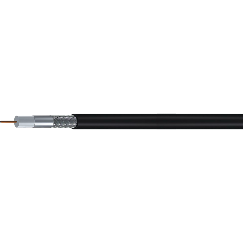
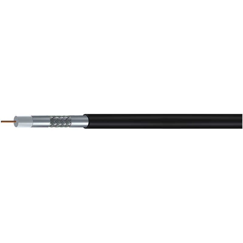
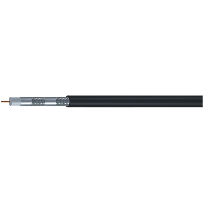
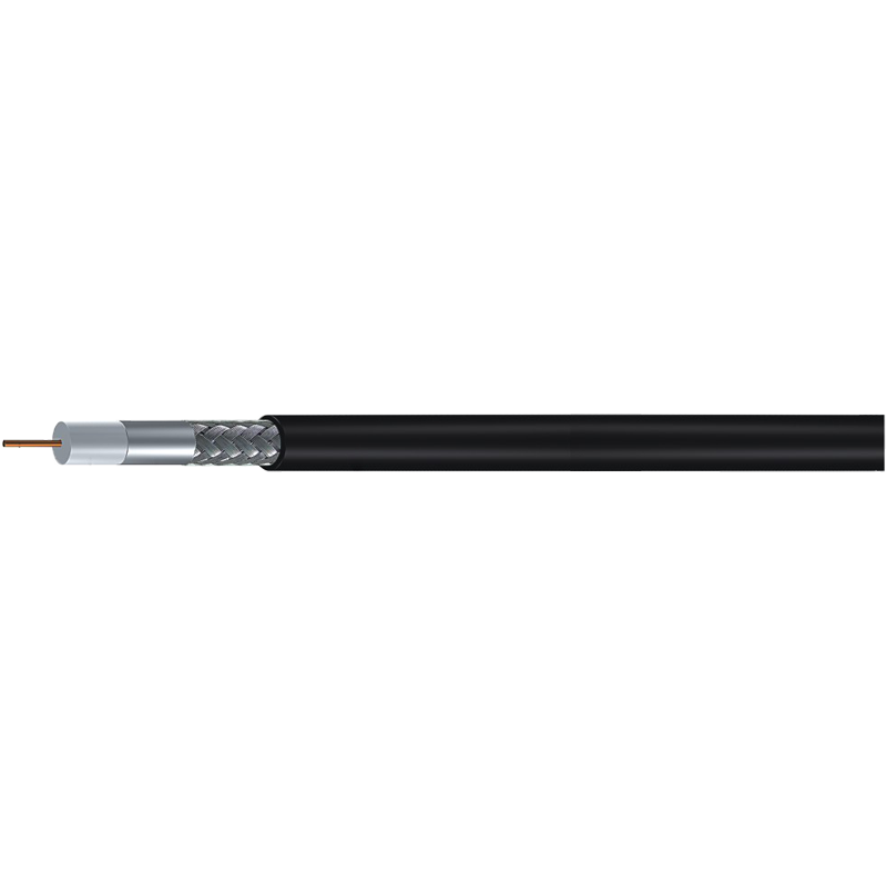
Every coaxial cable is engineered to present a specific characteristic impedance, determined by the ratio of the inner conductor diameter to the inner diameter of the shield, along with the dielectric material between them. This is one of the foundational elements of coaxial cable specifications, and it is not something you can change simply by using a different connector or adapter. A cable rated at 75 ohms and one rated at 50 ohms may look nearly identical on the outside, but their internal geometry is deliberately different to hit their target impedance value.
The Physics Behind the Number
When a signal traveling through a 50 ohm system suddenly meets a 75 ohm section, part of the energy reflects back toward the source instead of continuing forward. This reflected energy is what creates standing waves, raises VSWR, and produces the small mismatch loss discussed above. The mismatch does not "block" the signal — it simply causes a portion of it to bounce back rather than being delivered efficiently to the load.
The reflection coefficient for a 75-to-50 ohm junction works out to approximately 0.2 — a moderate mismatch by RF engineering standards, noticeable, but far from catastrophic.
Breaking Down the Numbers: VSWR, Return Loss, and Mismatch Loss
These three metrics all describe the same underlying phenomenon from different angles, and understanding them helps put the "how much loss" question into proper context.
| Metric | Approximate Value | What It Means |
|---|---|---|
| VSWR | 1.5:1 | Mild mismatch, generally tolerated by most transmitters |
| Return Loss | ~14 dB | About 4% of power reflected back toward the source |
| Mismatch Loss | ~0.18 dB | Reduction in forward power delivered to the load |
A VSWR of 1.5:1 is well within the range that most amplifiers and transceivers tolerate without automatic power foldback. For comparison, many manufacturers consider anything under 2:1 to be acceptable for continuous operation, so a single mismatched connector rarely puts hardware at risk.
Cable Attenuation Adds a Second Layer of Loss
The mismatch loss described above is only part of the picture. The cable itself has its own inherent attenuation, which is separate from the impedance mismatch and depends heavily on the cable's construction and the sizes of coaxial cable involved. Thicker cables with lower-loss dielectric materials attenuate the signal less per foot than thinner, cheaper alternatives, regardless of whether they are rated at 50 or 75 ohms.
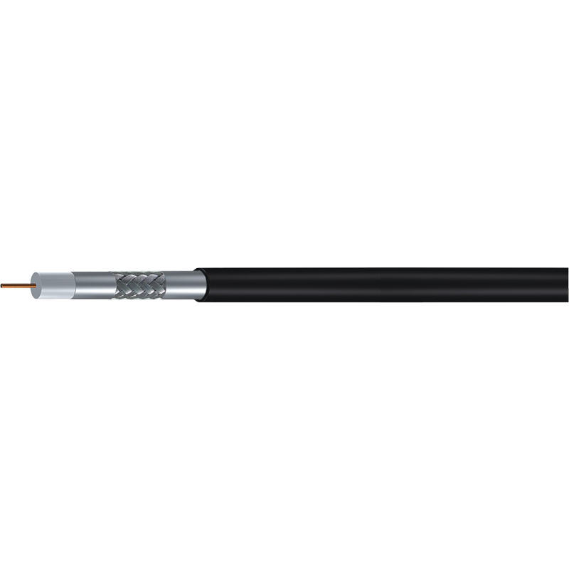
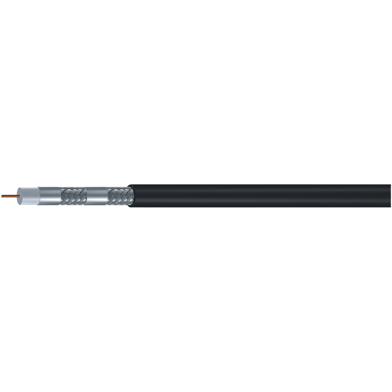
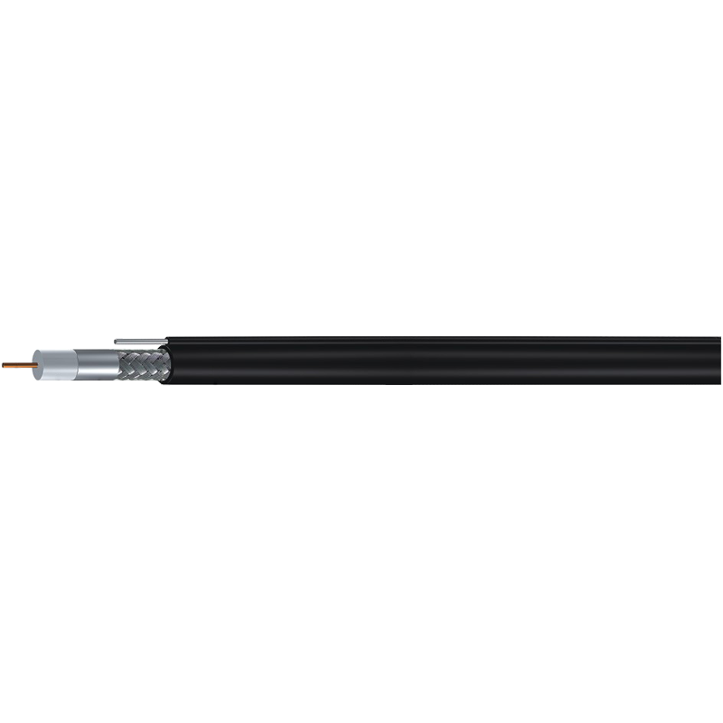
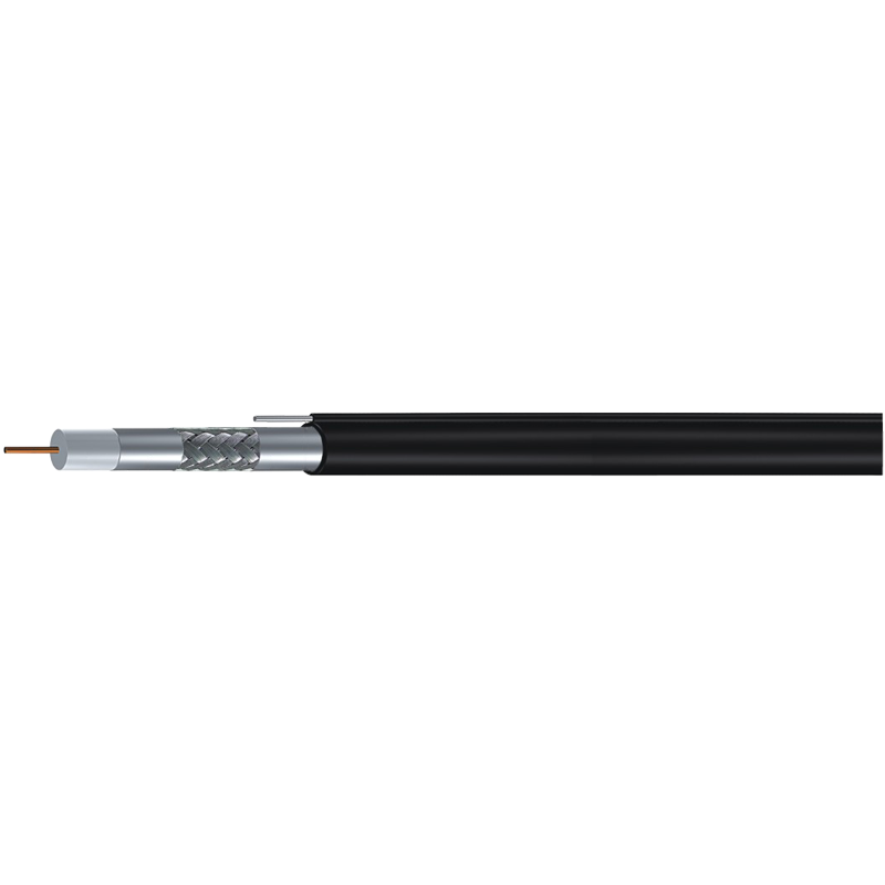
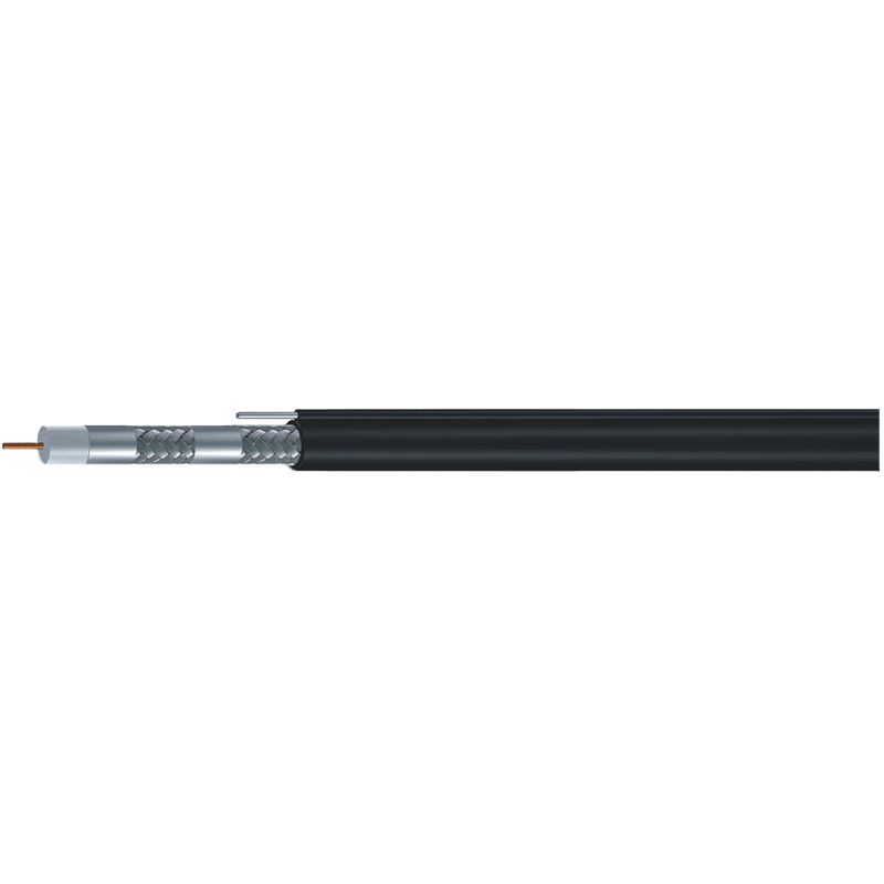
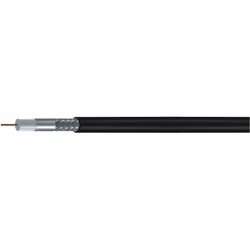
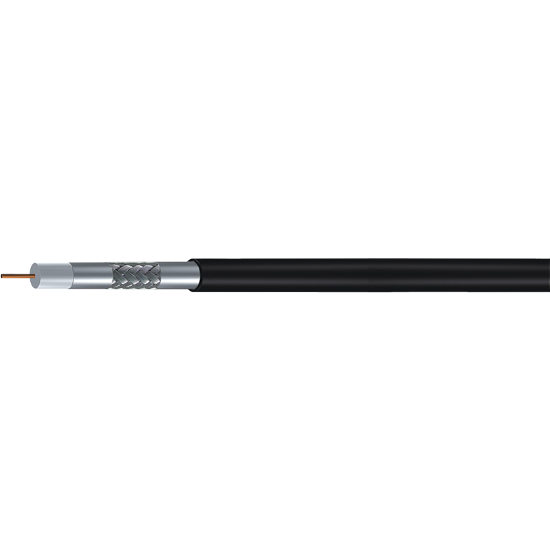
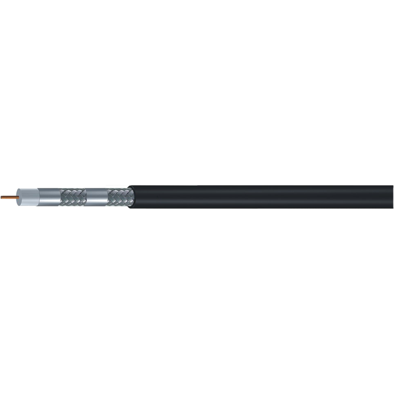
75 ohm coax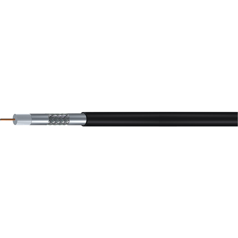
Frequency Makes a Real Difference
Attenuation is not constant across the spectrum — it increases with frequency. This is why the same cable that performs adequately at HF frequencies can show significantly more loss at VHF or UHF. Combined with the mismatch loss, the total signal degradation becomes more noticeable the higher you go in frequency.
| Frequency Range | Mismatch Loss Impact | Practical Effect |
|---|---|---|
| Below 30 MHz | Minimal, near 0.1–0.2 dB | Rarely noticeable in normal use |
| 30–300 MHz | Slightly compounded by cable attenuation | May affect weak-signal receive performance |
| Above 300 MHz | More pronounced, especially over longer runs | Can meaningfully reduce effective range or signal-to-noise ratio |
Info
Mismatch loss is a fixed, one-time penalty from the impedance step itself — it does not multiply with cable length the way ordinary attenuation does.
Comparing Cable TV Coaxial Cable to 50 Ohm Feedline
A common real-world scenario involves reusing leftover cable tv coaxial cable — typically 75 ohm, often labeled with a common designation you may recognize from home installations — for a 50 ohm application like an amateur radio antenna or a scanner feedline. This is technically possible and won't damage most receivers, but it will not perform identically to properly rated 50 ohm cable.
The good news is that cable tv coaxial cable is often manufactured to tight coaxial cable standards with excellent shielding and low attenuation per foot, since it needs to carry high-frequency television signals reliably over long distances. In some cases, its raw attenuation performance can actually rival or exceed cheaper 50 ohm alternatives — the tradeoff is purely the impedance mismatch, not necessarily overall cable quality.
How Cable Dimensions Influence the Total Picture
Coaxial cable dimensions play a larger role in real-world signal loss than most users expect. A larger center conductor and a larger overall cable diameter generally reduce resistive losses, which is why bigger cables tend to outperform thinner ones at the same frequency, independent of their impedance rating.
- Thin, flexible patch cables — convenient but higher loss per foot, so mismatch effects become a smaller fraction of total loss
- Medium-sized general purpose cables — balanced loss and flexibility, most common for home and hobbyist installations
- Larger, low-loss cables — minimal attenuation over distance, meaning the impedance mismatch becomes proportionally more significant in the total loss budget
This means that with premium, low-loss cable, the 0.18 dB mismatch penalty can represent a larger share of your total system loss simply because the baseline attenuation is already so low.
When the Loss Actually Matters in Practice
Short Jumpers and Patch Cables
For a short jumper of a few feet connecting a receiver to an antenna, the 0.18 dB mismatch loss is essentially imperceptible in normal use. Most users will not notice any practical difference in signal strength or audio quality.
Success
Short receive-only jumpers are effectively risk-free — the mismatch loss falls well below the threshold of audible or measurable difference in everyday listening.
Long Transmit Runs
Over a long run — say, 100 feet or more feeding a transmitting antenna — the combined effect of mismatch loss and any increase in cable attenuation can add up to a fraction of a decibel that's worth avoiding, particularly if you're already operating near your power or budget limits.
High-Power Transmitters
At higher power levels, reflected energy from the mismatch travels back toward the transmitter's final amplifier stage. While a VSWR of 1.5:1 is generally safe, some solid-state amplifiers with aggressive SWR protection circuits may reduce output power slightly as a precaution, which could be misread as a hardware fault.
Warning
If your transmitter's power output drops unexpectedly after a cable change, check for SWR-triggered foldback before assuming a hardware fault — it is a frequent and easily overlooked cause.
Reducing or Eliminating the Mismatch Loss
If the application is sensitive enough that even 0.18 dB matters, there are practical ways to address it:
- Use an impedance-matching transformer rated for the frequency range in use, which can bring the return loss down significantly
- Replace the mismatched section with properly rated cable if the run is long or the application is transmit-heavy
- Keep any mismatched sections as short as possible, since the reflection itself is a fixed one-time penalty rather than something that compounds with cable length
- Verify actual performance with a VSWR meter or antenna analyzer rather than relying solely on calculated estimates, since connector quality and cable condition also affect real-world results
Danger
Do not assume a matching transformer solves everything at every frequency — most are only rated for a specific band, and using one outside its intended range can introduce more loss than the mismatch it was meant to fix.
Practical Takeaway for Everyday Users
For the vast majority of casual, receive-only, or short-run applications, using 75 ohm coax on a 50 ohm system results in a loss so small that it won't be noticeable without test equipment. The roughly 0.18 dB mismatch loss and 1.5:1 VSWR are well within the tolerance of most consumer and hobbyist gear.
Where it becomes worth addressing is in longer transmit runs, high-power setups, or situations where you're already chasing every fraction of a decibel of performance. In those cases, matching the coaxial cable specifications to your system's actual impedance — rather than relying on whatever cable happens to be on hand — remains the more reliable long-term choice, especially when following established coaxial cable standards for the application at hand.