Coaxial Cable Engineering
Coaxial Cable Impedance: Why 50 Ohm and 75 Ohm Rarely Forgive a Mismatch
Characteristic impedance comes from geometry and dielectric, not from price. Here is how 50 and 75 ohm systems behave, what a mismatch actually costs, and which numbers belong in a purchase specification.
A CCTV installer terminates a 75 ohm RG6 drop with a 50 ohm BNC adapter because the parts drawer sits closer than the stockroom. The picture is clean on day one. Three weeks later the client reports faint horizontal banding, and the camera is blamed first, the recorder second, and the cable last.
The short version, before the detail: every element in the chain has to agree on impedance, including the cable, the connector and the equipment port. When they do not, part of the signal reflects back down the line instead of reaching the receiver, and those reflections grow more damaging as frequency rises and runs get longer.
What follows covers what characteristic impedance really is, why the industry settled on 50 and 75 ohms, how a mismatch shows up on test gear and on a screen, and what to write into a specification so the problem never reaches the site.
What Coaxial Cable Impedance Actually Measures
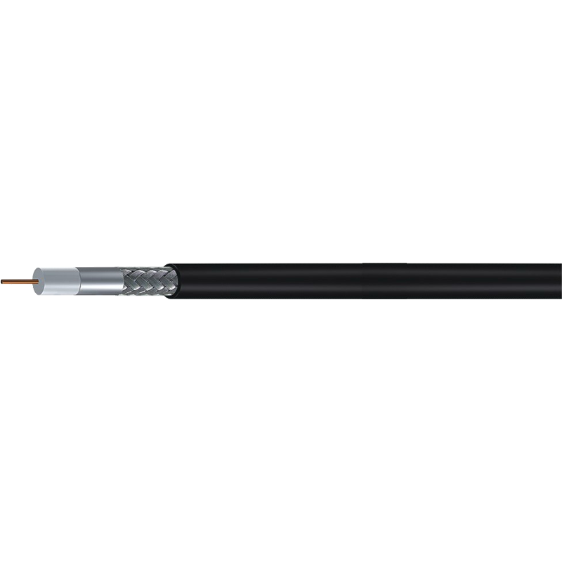
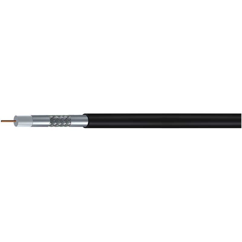
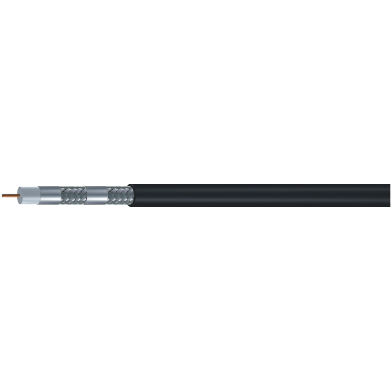
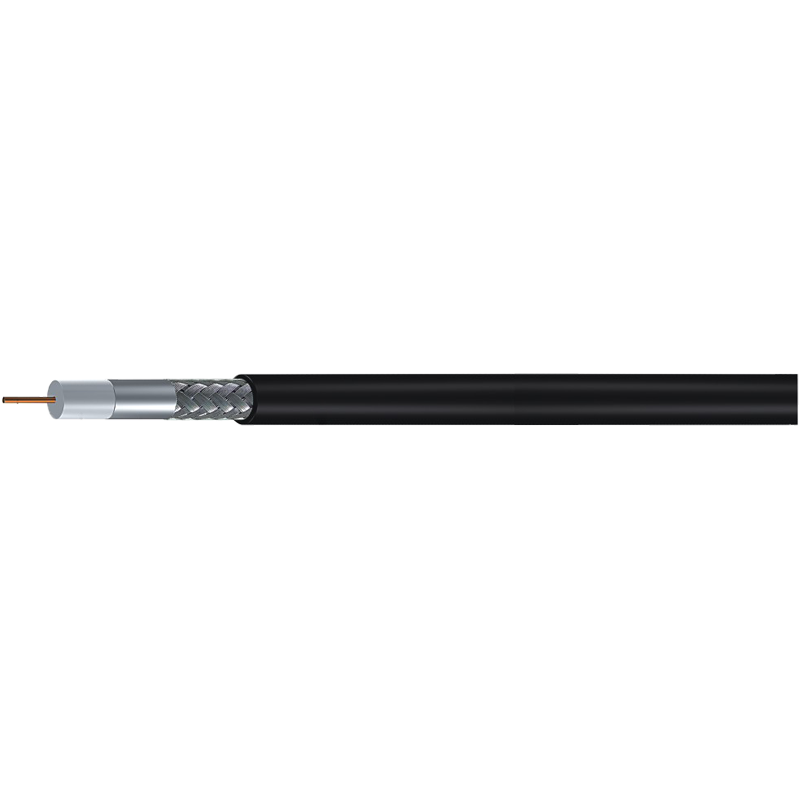
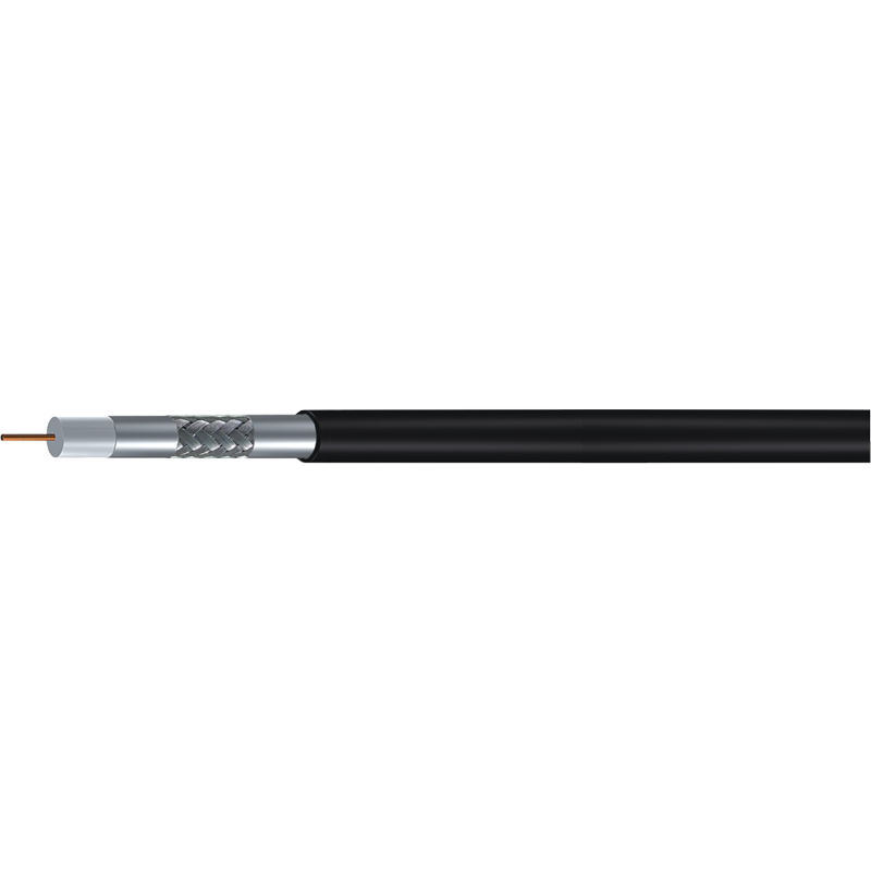
Characteristic impedance is not resistance. It is the ratio of voltage to current for a wave travelling along the line, and it exists even when nothing is connected at the far end. In the physical build of a coaxial cable it is set by three things: the diameter of the centre conductor (d), the inner diameter of the shield or of the dielectric that fills the space (D), and the dielectric constant of that material.
For a coaxial line, the classic working formula is Z0 = 138 divided by the square root of the dielectric constant, multiplied by the base ten logarithm of D divided by d. Move the conductor and shield further apart, or lower the dielectric constant, and impedance rises.
Two consequences matter commercially:
- Impedance does not change with length. A 5 m and a 500 m piece of the same RG6 both sit at about 75 ohm.
- Impedance cannot be read with a multimeter. Verifying it needs a time domain reflectometer, a network analyser, or a sweep test against a known load.
DC resistance is a separate specification, and it still matters. A satellite receiver pushing LNB power up a long run has to overcome loop resistance, something impedance says nothing about.
Characteristic impedance describes the travelling wave, so it applies along the whole cable rather than at one point on it. A cable is matched only when the source, the line and the load all share the same impedance.
Why 50 Ohm and 75 Ohm Became the Standards
Neither number is arbitrary. In air dielectric coax, attenuation is lowest near 77 ohm, while power handling peaks near 30 ohm. Microwave engineers needed both low loss and usable power, so 50 ohm became the working compromise and hardened into military and later commercial practice. Broadcast engineers cared about low loss on long, low power video runs, so 75 ohm, sitting closer to the attenuation minimum, became the video and cable television standard.
Fifty ohms is a compromise between power and loss; seventy-five ohms leans toward loss. Both are engineering choices, not quality grades.
The visible differences sit mainly in power handling and connector families, as the comparison below sets out.
| Characteristic | 50 ohm | 75 ohm |
|---|---|---|
| Typical applications | Wireless and RF links, antenna feeders, LTE, test equipment | CATV, MATV, satellite IF, CCTV, baseband video |
| Common connector families | BNC 50 ohm, N, SMA, TNC | F, BNC 75 ohm, video RCA |
| Power handling | Higher | Lower |
| Attenuation at comparable geometry | Slightly higher | Slightly lower |
| Distance from the loss minimum near 77 ohm | Further | Closer |
| Typical cable examples | RG58, RG174, RG213, LMR400 | RG6, RG59, RG11, S5CFB |
| Published impedance tolerance | Often about 2 ohm | Often about 3 ohm |
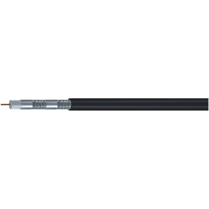
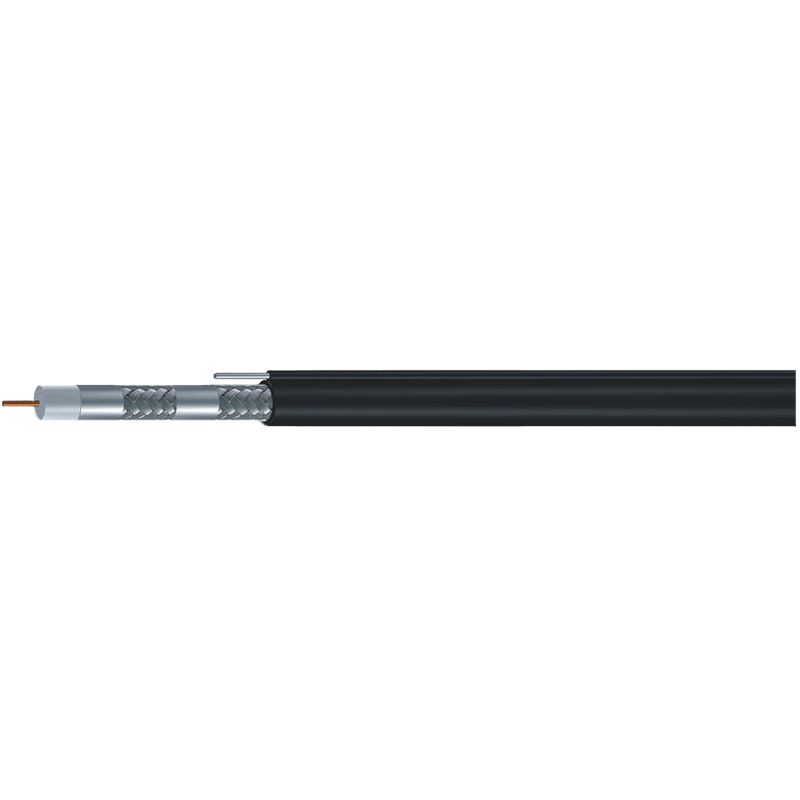
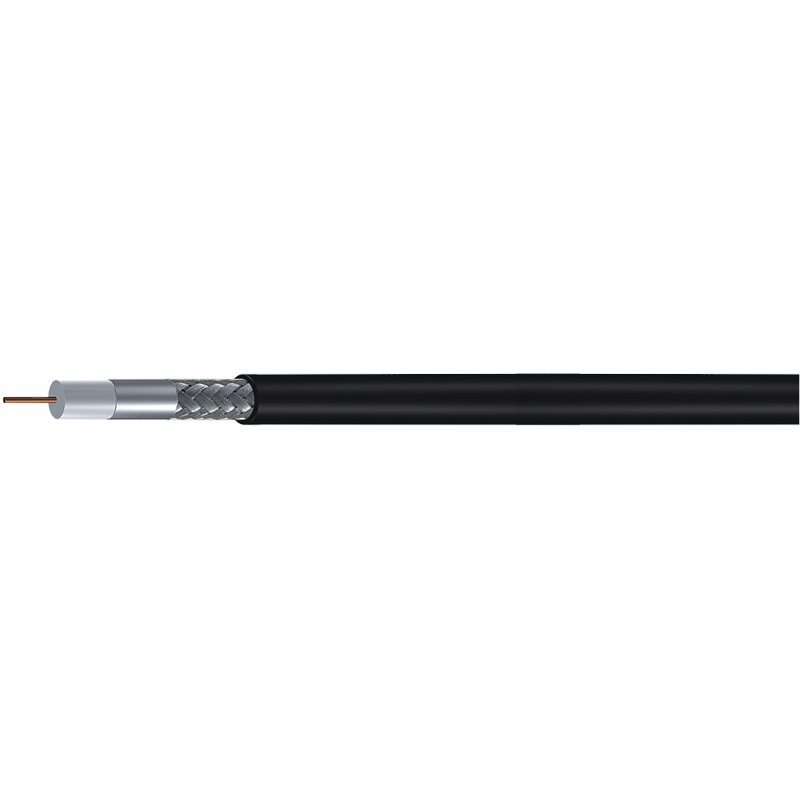
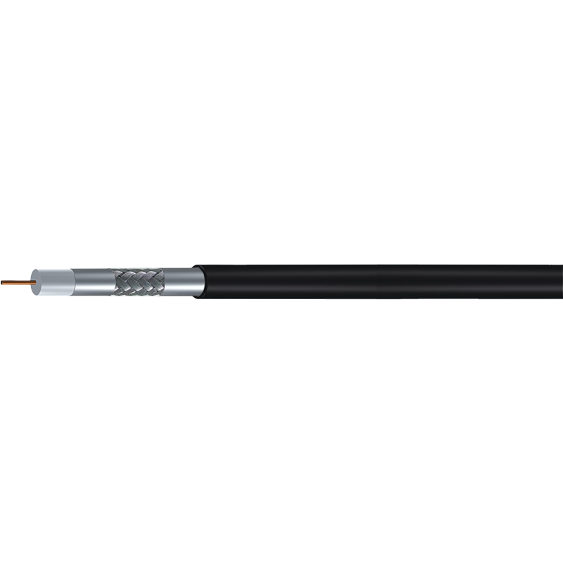
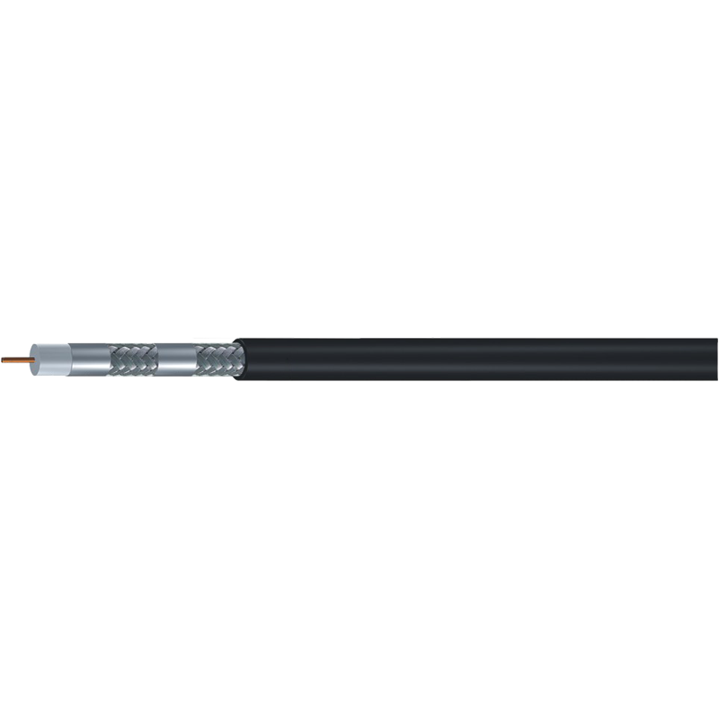
For 75 ohm distribution work, the shielding structure is usually the next decision after impedance. Standard shield suits short subscriber runs, tri-shield adds a foil plus braid for noisier environments, and quad-shield is chosen where ingress and return loss margins are tight.
Mismatch in Numbers: Return Loss, VSWR and Visible Symptoms
Reflection is predictable. Feed a 75 ohm load from a 50 ohm source and the reflection coefficient is 0.2, which is a VSWR of about 1.5 to 1, a return loss near 14 dB, and roughly 4 percent of the incident power reflected. Four percent sounds harmless, and on a short patch lead it usually is. On a 300 m trunk, or in a dense channel lineup, it is not, because the reflected wave arrives late and then adds to or subtracts from the direct signal.
Impedance errors tend to announce themselves in a few recognisable ways:
- Faint ghosting, ringing, or a second edge on analogue video
- Banding, sparkle, or intermittent dropouts on digital CATV and IPTV channels
- A rising error rate at the headend that no amplifier adjustment fixes
- A VSWR alarm at a transmitter that tests clean into a dummy load
- A link that passes once and fails when another device joins the chain
Fifty and seventy-five ohm connectors of the same family are not interchangeable, even when they appear to mate. A 75 ohm BNC carries a thinner centre pin than a 50 ohm BNC. Forcing the wrong plug spreads the socket contact or leaves a loose joint, which stacks a mechanical fault on top of the electrical one.
Matching Impedance to the Installation
Most impedance errors happen at handover points rather than inside the cable. Set the requirement from the application first:
- Satellite IF and DTH: 75 ohm from LNB to receiver, with F connectors. DC power for the LNB travels on the same centre conductor, so loop resistance and impedance both belong in the specification.
- CATV, MATV and IPTV distribution: 75 ohm throughout. RG11 for aerial drops and long trunks, RG6 for typical subscriber runs, RG59 for short patches behind equipment.
- CCTV: 75 ohm across the video pair, including siamese constructions that carry DC power alongside the coax.
- Wireless and RF links: 50 ohm throughout. RG58 for short jumpers, RG213 or LMR400 where a longer feeder run would otherwise consume the link budget.
Where a system genuinely has to cross between domains, such as a 50 ohm radio driving a 75 ohm antenna system, use a matching pad or transformer rather than an adapter and hope. Impedance tolerance is also worth pinning down at this stage, because a cable that drifts several ohms from nominal behaves like a small mismatch at every joint along the run.
CCTV and Small Systems: Where 75 Ohm Errors Hide
Surveillance work tests impedance discipline hardest, because low cost adapters and mixed camera brands meet in the same cabinet. A composite CCTV run is 75 ohm from camera output, through the coax, to the recorder input, and a loose BNC or a stray 50 ohm adapter affects a short cable less than a long one.
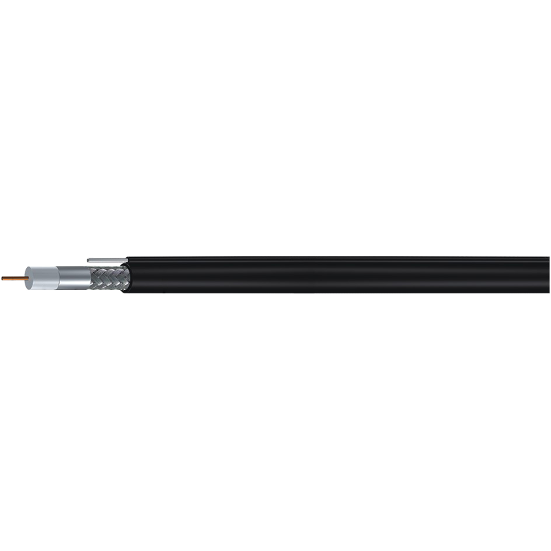
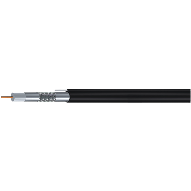
Siamese constructions such as KX6 with power, RG59 with power or RG6 with power place a 75 ohm video pair beside an 18 or 20 AWG power pair. That removes a separate power run, but it does not change the rule: terminate the coax as 75 ohm at both ends, with 75 ohm BNC or F connectors and no 50 ohm parts in between.
Keep the video path 75 ohm end to end: camera output, cable, connectors, patch panel and recorder input. Every 50 ohm adapter inserted into that chain adds a reflection the recorder cannot undo.
What to Check Before You Buy
Impedance is the easiest line on a datasheet to verify and the one most often taken on trust. Ask a supplier for six items before placing a production order:
- Nominal impedance and tolerance. A 75 ohm video cable quoted at plus or minus 3 ohm is normal; anything wider than plus or minus 5 ohm deserves questions.
- Sweep or structural return loss data across the band you will actually use, not a single frequency point.
- Velocity of propagation, typically 0.66 to 0.87 depending on whether the dielectric is solid or foamed, which drives timing and length calculations.
- Connector interface. Confirm 75 ohm F or 75 ohm BNC as required, and reject mixed 50 ohm hardware for video systems.
- Standards and compliance evidence, such as EN 50117 for CATV cables or JIS and MIL equivalents, plus UL, ETL, CE, CPR, RoHS or REACH where the project demands them.
- Consistency along the drum. The dielectric diameter that sets impedance has to stay stable for the whole length, so a sample test from both ends of a delivery is a reasonable check.
Impedance behaves like a chain: 50 or 75 ohm at every joint, or a reflection at every joint. Match the number to the application, using 75 ohm for video, CATV, satellite and CCTV, and 50 ohm for RF, wireless and test work, then make sure cables, connectors, adapters and equipment ports all agree. When a signal problem survives every other explanation, measure with a time domain reflectometer before replacing another camera.