Coaxial Cable Selection Guide: Impedance, Shielding, Distance, and Cost
Getting the cable wrong rarely shows up on day one. It shows up as dropped frames, snow on a channel, or a re-pull you pay for twice.
A 180 ft RG59 run to a 4K camera passes a bench test, then fails in a warehouse ceiling two weeks later. The cable is not defective. The run is too long for the loss budget, the center conductor is copper-clad steel, and the 12 V supply reaches the camera as something closer to 9 V.
Most coaxial faults blamed on bad cable trace back to a selection decision made in the wrong order: impedance chosen by habit, shielding chosen by price, conductor chosen by whatever was already on the shelf.
The short version is this. Settle impedance first, then shielding, then conductor and jacket for the real route, and only then compare cost per foot. Four decisions taken in that order prevent most of the expensive re-pulls.
Start With Impedance, Then Stop Comparing Brands
Impedance is fixed by the equipment at both ends of the link, not by preference. A 75 ohm video system and a 50 ohm radio system need different transmission lines, and the cable, the connectors and every adapter in between have to agree.
- 75 ohm: CATV, MATV, SMATV, DTV, IPTV, satellite TV distribution and CCTV video.
- 50 ohm: LTE and wireless networks, RF antenna feeders, and test equipment.
A mismatch does not simply weaken the signal. It reflects power back toward the source, raising VSWR on an RF link, eroding return loss and pushing bit error rates up on digital video. One 75 ohm jumper on a 50 ohm port can take a link out of specification even when the run is short.
| Consideration | 50 ohm | 75 ohm |
|---|---|---|
| Typical systems | LTE, wireless links, RF test, antenna feeders | CATV, MATV, DTV, satellite TV, CCTV video |
| Common families | RG58, RG174, RG213, LMR200, LMR400, 4DFB to 12DFB | RG6, RG59, RG11, S4CFB, S5CFB, S7CFB |
| Symptom of a poor match | High VSWR, reflected power, reduced link margin | Ghosting, level loss, unstable digital reception |
| Connector families | N-type, TNC, SMA | F-type, 75 ohm BNC |
Long RF runs and receivers with little margin are where the low-loss end of the 50 ohm range earns its cost. A thicker version of a lossy design rarely buys back what a lower-loss construction gives for free.
Match the Cable Family to the Application and the Run
With impedance fixed, the family follows from the application and the distance, not from whatever is already in the warehouse.
- RG59: short drops and patch leads; workable for HD only over short distances and with a solid copper center conductor.
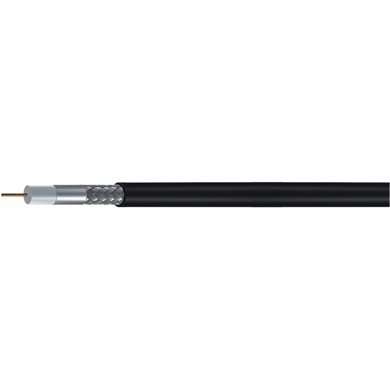
- RG6: the standard 75 ohm drop for satellite, cable TV and residential distribution, with an 18 AWG center conductor and better shielding than RG59.
- RG11: lower loss per 100 ft, used where tap-to-building or headend-to-node distance exceeds what RG6 carries cleanly.
- S4CFB, S5CFB and S7CFB: 75 ohm constructions for distribution work that needs lower attenuation or tighter tolerances.
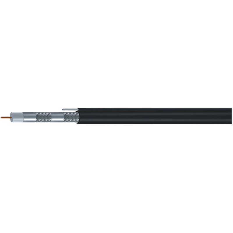
- 500 and 540 trunk series: backbone and distribution in a network, with messenger versions for aerial spans.
- CCTV composite cable: KX6, RG59 or RG6 with an integrated power pair, for cameras fed at the pole rather than at the panel.
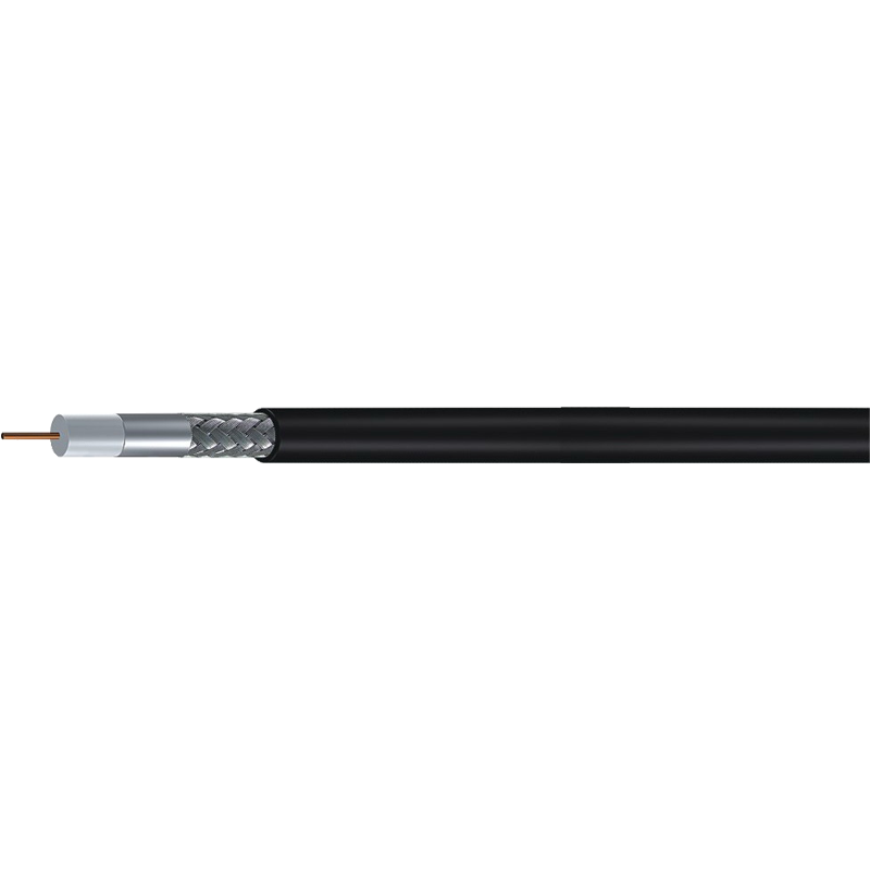
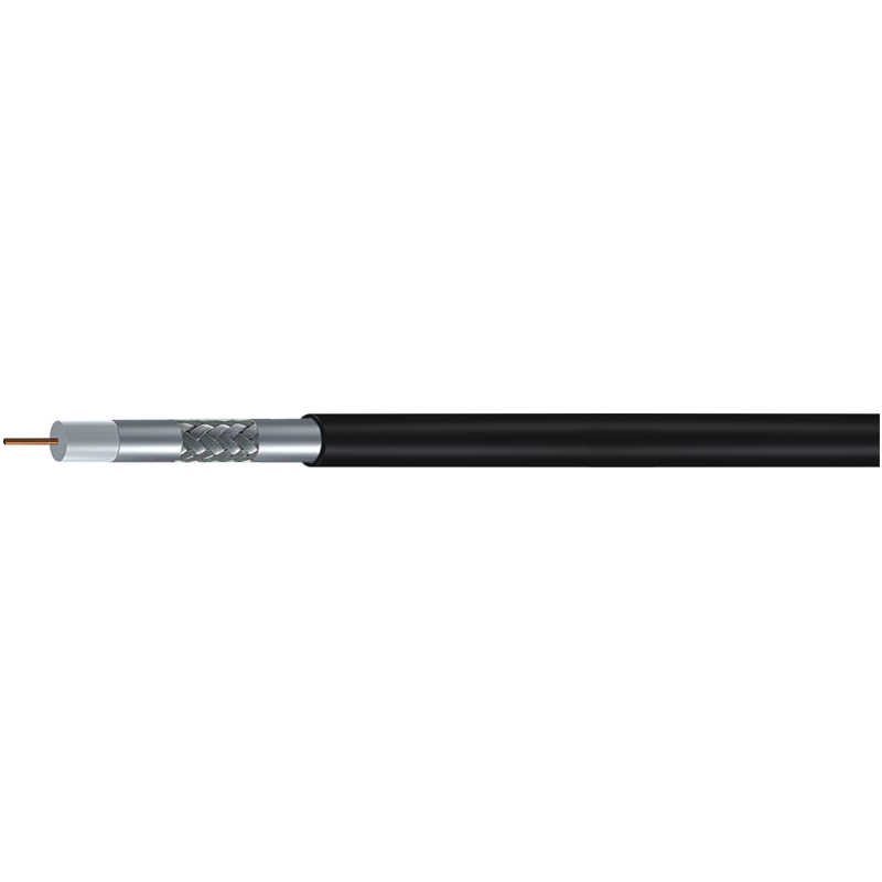
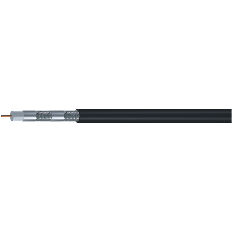
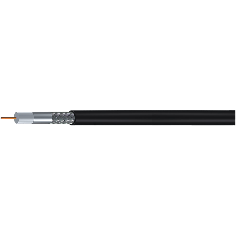
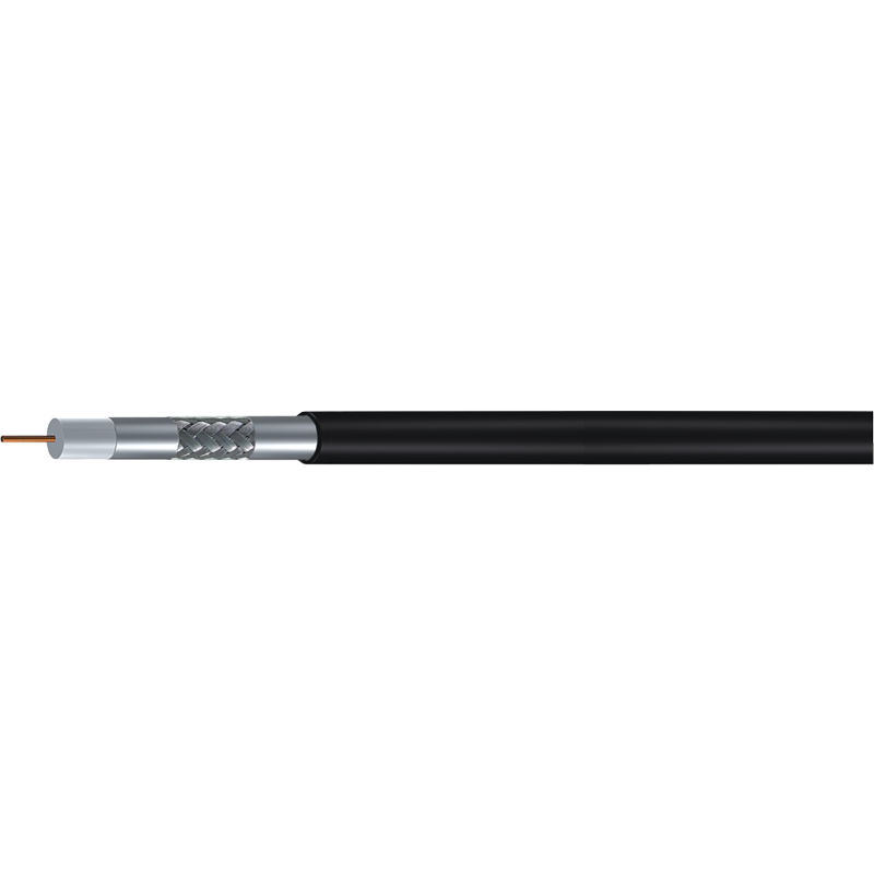
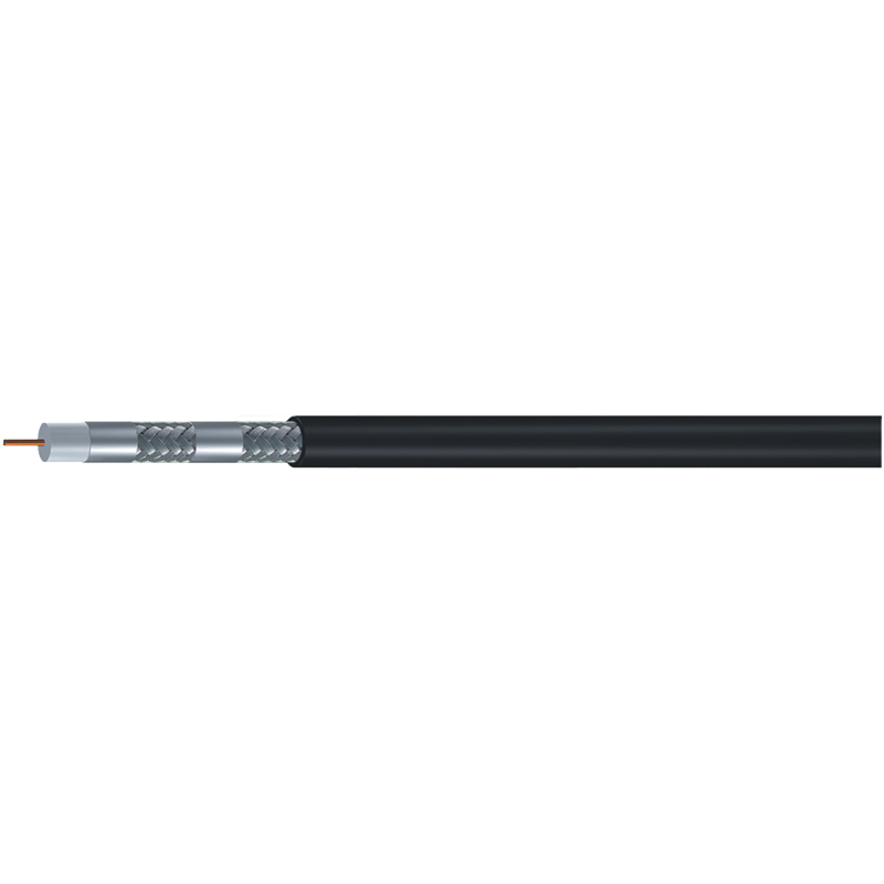
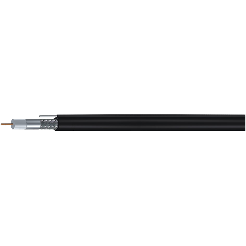
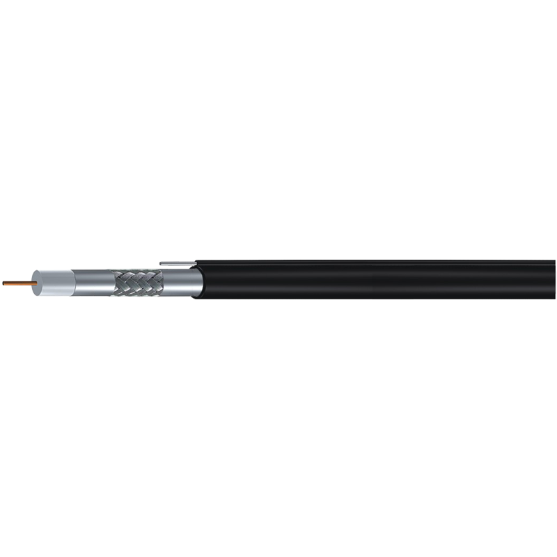
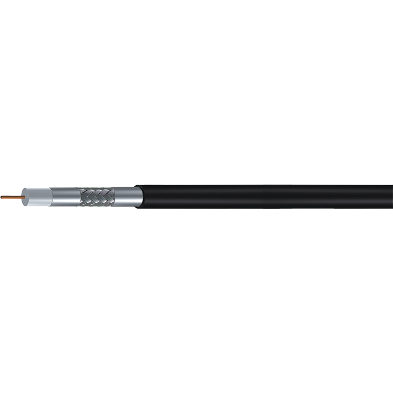
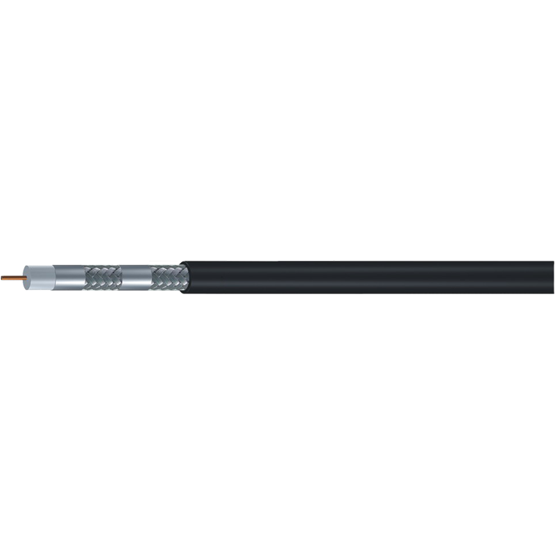
The 75 ohm coaxial cable range covers RG6, RG59 and RG11 in standard, tri-shield and quad-shield builds, with and without an attached messenger, so the same project can move from indoor drop to aerial span without changing supplier.
Shielding: Standard, Tri-Shield and Quad-Shield
Shield construction decides how much interference enters the cable and how much signal leaks out. It is not a quality tier; it is a fit to the electromagnetic environment.
- Standard shield: one foil plus one braid. Adequate for a clean residential drop.
- Tri-shield: foil, braid and a bonded foil layer. A sensible default where mobile transmitters or parallel power runs are close by.
- Quad-shield: two foils and two braids. The highest screening, and also the heaviest, stiffest and slowest to terminate.
Over-specifying shielding carries a real cost. Quad-shield on a short indoor patch adds stiffness and termination time for no measurable benefit, while standard shield on a long run beside a cellular antenna invites ingress that no amplifier can remove afterwards.
A shield only performs if it is terminated properly. Foil and braid bonded to a poorly fitted connector behave like an antenna rather than a screen.
Conductor Material, Gauge and the Loss Budget
Attenuation is quoted in dB per 100 ft at a given frequency, and the frequency that matters is the highest one in the system, not the average. Add every element in the chain: cable, connectors, splitters, wall plates and patch leads.
Center conductor material changes the arithmetic more than most buyers expect. Solid bare copper gives the lowest resistance. Copper-clad steel is common in short residential drops and performs acceptably there, but its higher DC resistance costs voltage on long power-over-coax runs and adds loss at higher frequencies.
Gauge follows the same logic. RG59 usually runs a 20 or 22 AWG center conductor, RG6 an 18 AWG, RG11 a 14 AWG. When a calculated end-of-line level sits within a couple of dB of the receiver minimum, no margin is left for moisture, ageing or one badly fitted connector.
Check the conductor before comparing price per foot. On a 250 ft combined video and power run, copper-clad steel can put a camera below its minimum input voltage while the cable still tests fine on the bench.
Jacket, Messenger and the Physical Route
The route decides the jacket. Indoor PVC suits ordinary riser spaces, while polyethylene is the usual outdoor choice because it resists UV and moisture. Where a building code demands limited fire propagation, specify a compliant jacket rather than assuming one.
Aerial spans need support. Integrated messenger versions of RG6, RG11 and the 500 and 540 trunk series carry their own steel strand, which removes the need for a separate catenary wire and keeps the cable under controlled tension.
Staples and over-tight clips deform the dielectric. A crushed spot changes local impedance and returns a reflection that no amount of shielding will absorb.
Connectors and Termination Decide the Last Few dB
Every connector is a small impedance discontinuity. F-type compression fittings suit 75 ohm video, 75 ohm BNC suits professional video, and N-type suits 50 ohm RF. Fitting a 50 ohm BNC onto a 75 ohm line adds a reflection at both ends of the link.
Outdoor connections fail more often than cables do. Weatherproof the joint, use the connector body the cable was dimensioned for, and keep the number of splices low enough that the loss budget still closes.
Compliance and Test Data to Ask For
On export projects, compliance is a gate rather than a preference. UL and ETL matter for North America, CE and CPR fire classification for the EU, and RoHS and REACH cover restricted substances. JIS and ISO 9001 or 14001 speak to management systems and process control.
Ask for evidence rather than claims:
- Attenuation against frequency, measured at the highest system frequency rather than at 100 MHz alone.
- Return loss or structural return loss for the finished assembly.
- Conductor DC resistance and a material declaration.
- Jacket material datasheet, including UV and fire performance.
- Batch traceability, so a field failure can be traced back to a production lot.
A quotation that arrives with a frequency-sweep attenuation report attached usually belongs to the supplier who also passes first-article inspection.
A Practical Selection Sequence
- Confirm the system impedance and the highest frequency the link will carry.
- Measure the real route, including slack and vertical drops.
- Calculate the loss budget with cable, connectors, splitters and patch leads included.
- Choose the family and gauge that leave margin at the far end.
- Match the shield to the interference environment rather than to the price list.
- Pick the jacket and messenger for indoor, outdoor, duct or aerial installation.
- Verify certification, test data and lot traceability before releasing the order.
Coaxial cable selection is mostly about refusing to optimise the wrong variable. Cost per foot is the last number to compare, not the first, because a reel that fails a loss budget or a fire classification turns out to be the most expensive item on the quotation.
If you want to run this logic against a specific system, the walkthrough in how to choose coaxial cable follows the same order and covers the trade-offs between families in more detail.