Cable Engineering Note
Coaxial Cable Diagram: A Field Guide to Every Layer
Signal quality is decided before the connector goes on. Here is how to read the drawing, compare the layers, and choose the right coax for the job.
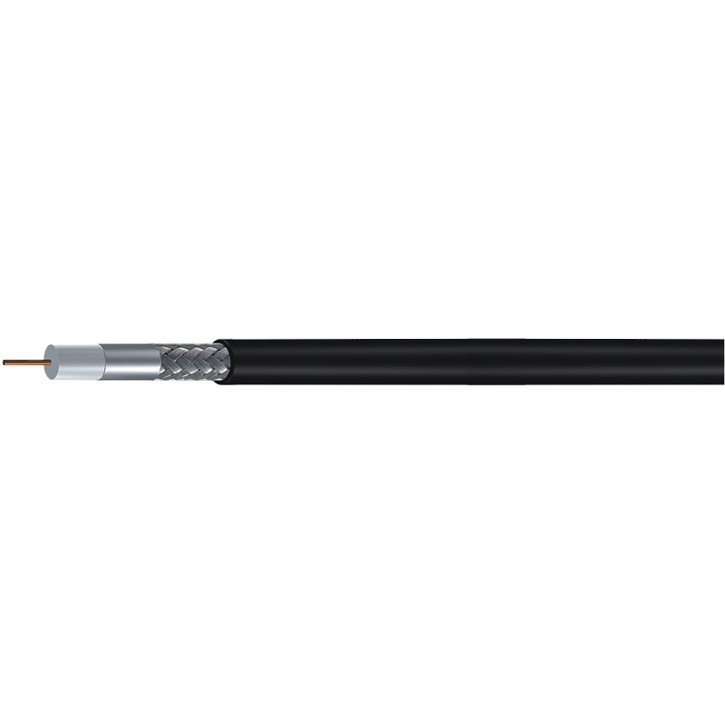
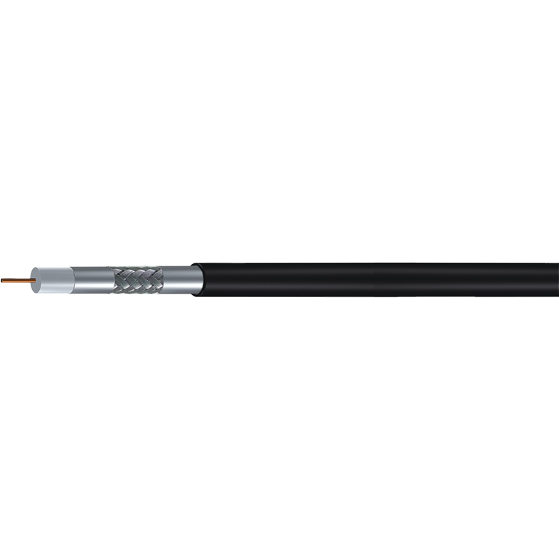
Every coaxial cable diagram starts as a set of concentric circles: a thin center conductor, a thick dielectric ring, a layered shield, and an outer jacket. If you are about to run cable for a satellite dish, a security camera, or a broadband gateway, this drawing can tell you whether the signal will arrive clean or fade into noise. In short, a coax diagram is a cross-section of four engineered layers, and the material, thickness, and shielding of those layers decide how far the signal can travel and how much interference the cable can reject.
What a Coaxial Cable Diagram Really Shows
The four rings are not just protection; they form the transmission line. Each layer has a specific electrical job, and when any layer is wrong for the application, the entire link suffers.
| Layer | What it does | Typical material | What failure looks like |
|---|---|---|---|
| Center conductor | Carries the RF signal current | Solid bare copper, copper-clad steel, or stranded copper | Corrosion, kinks, or thinning raise loss and cause reflections |
| Dielectric | Keeps the center conductor exactly spaced from the shield | Foamed polyethylene (FPE), solid polyethylene, or PTFE | Moisture or deformation changes impedance and attenuation |
| Shield | Confines the signal and rejects external interference | Aluminum foil, braided copper, or a combination | Broken braid wires allow leakage, ghosting, and noise |
| Jacket | Provides mechanical and weather protection | PVC, PE, or low-smoke, halogen-free compound | Cracks let in water and slowly destroy the cable |
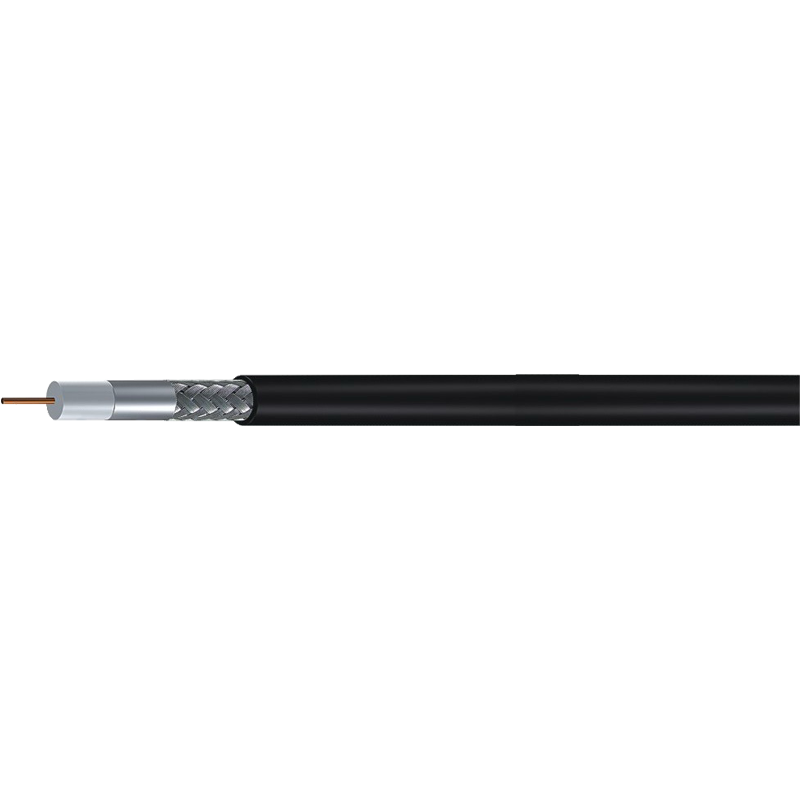
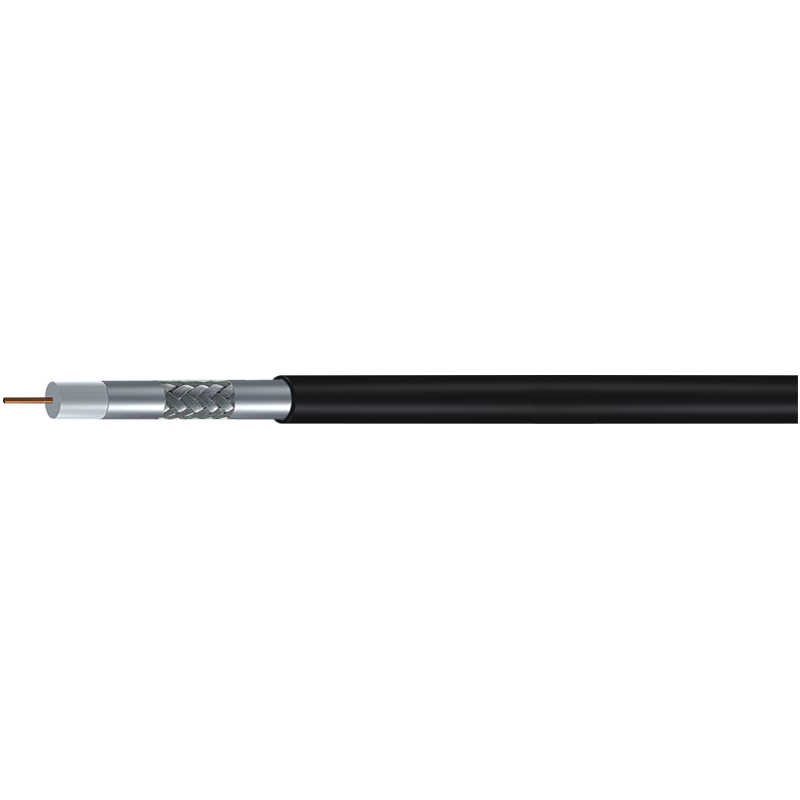
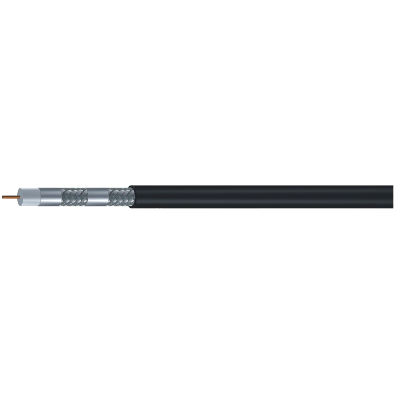
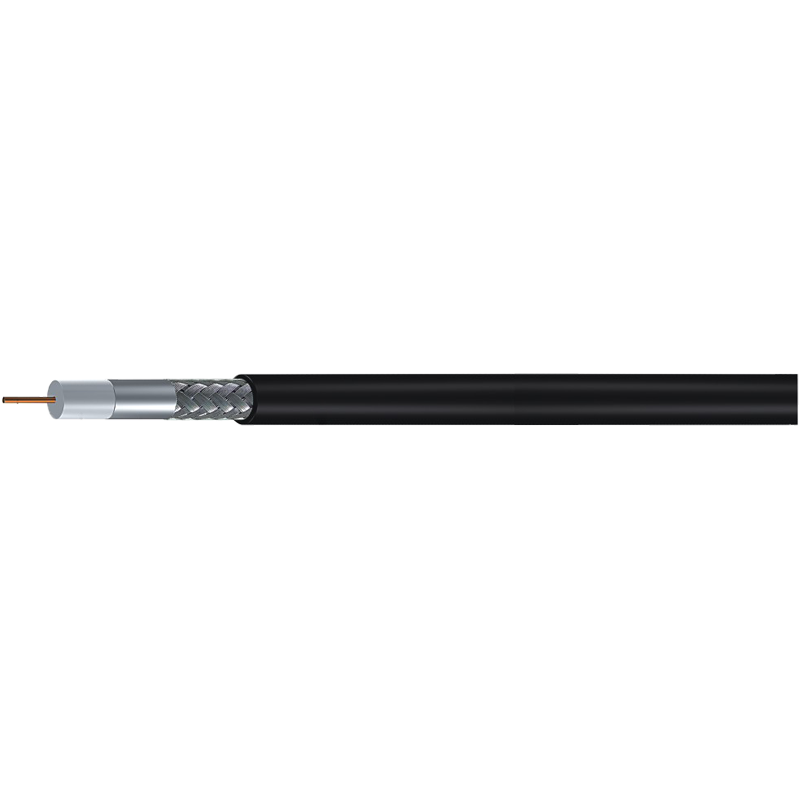
When you compare two diagrams, start with the thickness of the dielectric and the structure of the shield. A quad-shield RG6, for example, shows extra foil and braid rings beyond a standard-shield cable. That extra shielding matters near radio base stations, elevators, or any environment with strong interference.
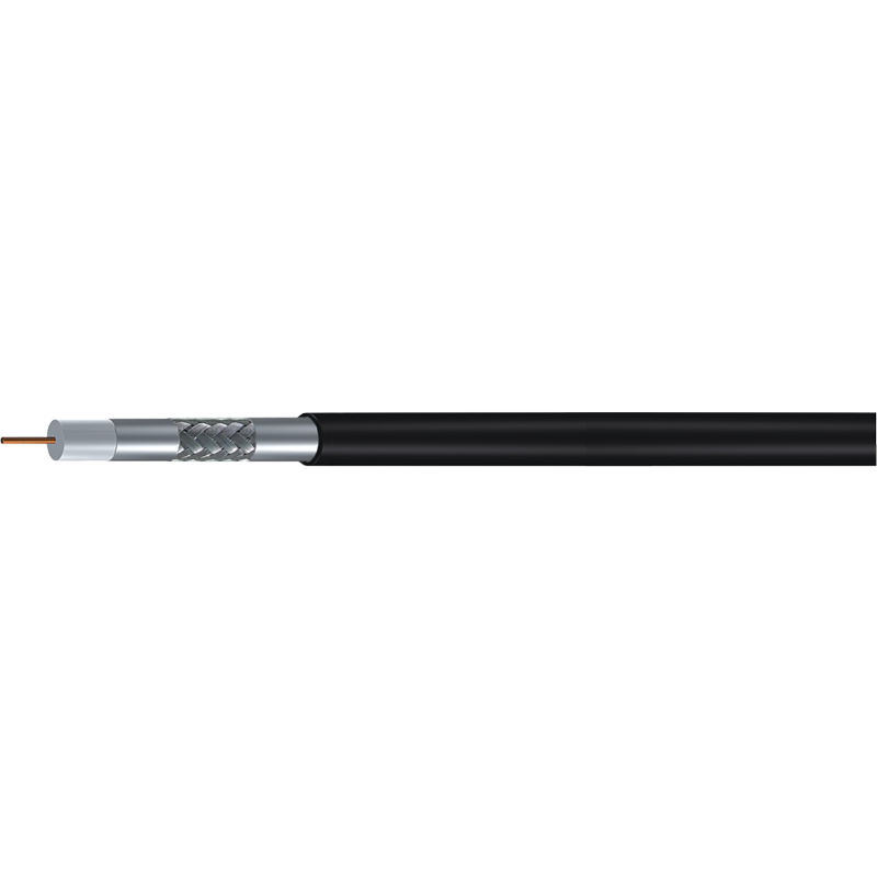
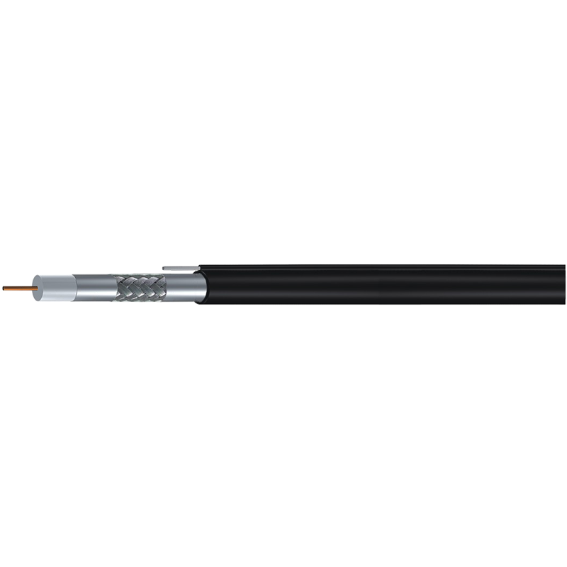
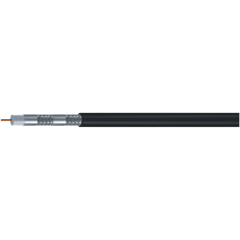 RG6 Quad-Shield 75 Ohm Coaxial Cable with Foam PE DielectricThis cable's quad-shield construction adds extra foil and braid layers, useful in high-interference environments. The diagram highlights dielectric spacing and shield structure that determine impedance and signal reflection.View Product →
Why the Concentric Design Matters
The concentric geometry is what turns a copper wire into a controlled transmission line. The center conductor and the shield form one continuous channel for the signal. The dielectric keeps them at a fixed distance, and that distance sets the characteristic impedance. Change the spacing, and part of the signal reflects back toward the source instead of continuing down the line.
Every experienced installer I know ends up repeating the same rule when they look at a coaxial cable diagram: the shield is part of the signal path, not an accessory. If you nick the dielectric or break the braid, you are changing the drawing.
Characteristic impedance is written into the geometry. A 75-ohm cable is optimised for video, cable television, satellite distribution, and broadband data. A 50-ohm cable, with a relatively thicker center conductor, is common for RF and wireless transmitters. The same diagram structure appears in both, but the proportions tell you which world it was built for.
50 ohm vs. 75 ohm. In a 50-ohm coax, the center conductor is thicker relative to the overall diameter, which supports higher power handling. In a 75-ohm coax, the proportions are tuned for lower attenuation on video and carrier frequencies. A quick look at the drawing will usually reveal which family you are holding.
The physics is covered in more detail in this introduction to coaxial cable electrical behaviour, but for daily installation work, the drawing is enough to predict how the cable will behave.
Different Diagrams, Different Coax Families
The familiar labels RG59, RG6, and RG11 are easier to decode once you see the diagram. RG59 uses a thin center conductor and a small dielectric; it is fine for short analog video runs. RG6 increases the center conductor and dielectric sizes, which lowers attenuation at the frequencies used by satellite TV and cable modems. RG11 goes further in both dimensions and delivers the lowest loss per metre, at the cost of a thicker, stiffer cable.
The same product name appears under several shield configurations. Standard-shield, tri-shield, and quad-shield versions simply add alternating layers of foil and braid to the diagram. More layers improve shielding against interference, but they also make the cable less flexible and slightly more expensive. Choose the shield structure according to the noise environment, not just the label.
For long outdoor spans, RG11’s thicker dielectric and heavier shield provide the margin that RG6 cannot deliver, especially when the cable must cross open space or run between buildings.
A 50-ohm cable will not appear under a 75-ohm part number, but its diagram is similar. The main difference is the larger center conductor and lower-loss dielectric, which suit RF feeders and wireless equipment. Keep the two families separate; impedance compatibility matters more than price.
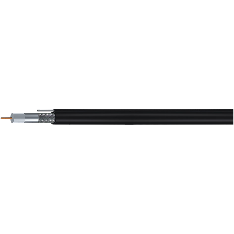
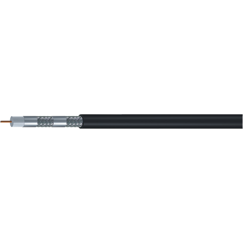 RG11 Quad-Shield 75 Ohm Coaxial Cable with Larger ConductorWith a thicker center conductor and gas-injected foam dielectric, this cable suits longer runs or lower-loss needs. The section compares it to RG6 and emphasizes checking impedance compatibility with your system.View Product →
Choosing by What the Diagram Promises
Start the selection with the amount of signal loss you can tolerate and the noise level at the site. These two numbers are not found in a datasheet alone; they are visible in the diagram.
- Short indoor runs up to 50 ft: an RG59 with a standard shield is often enough for CVBS or older analog signals.
- Residential video and broadband: a quad-shield RG6 is the practical balance between loss, flexibility, and termination ease.
- Long outdoor or vertical runs: choose RG11, a trunk cable, or a messenger version that carries its own support strand.
- CCTV cameras at distance: consider a composite coax with an integrated power pair, so the installation needs only one pull.
Before ordering, walk through the step-by-step coax selection guide to compare attenuation tables, connector compatibility, and mechanical requirements. It is faster than guessing and returns a better cable every time.
The payoff. When the impedance, shield density, and mechanical form match the environment, the system usually works without an amplifier or signal conditioner. The extra time spent reading the diagram pays for itself in fewer site visits.
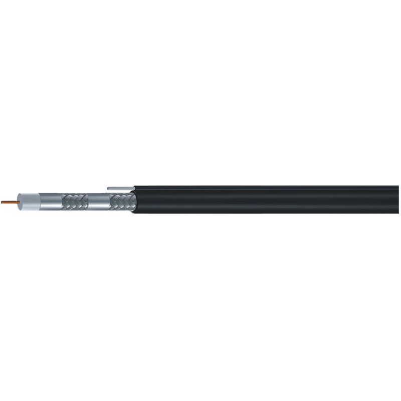
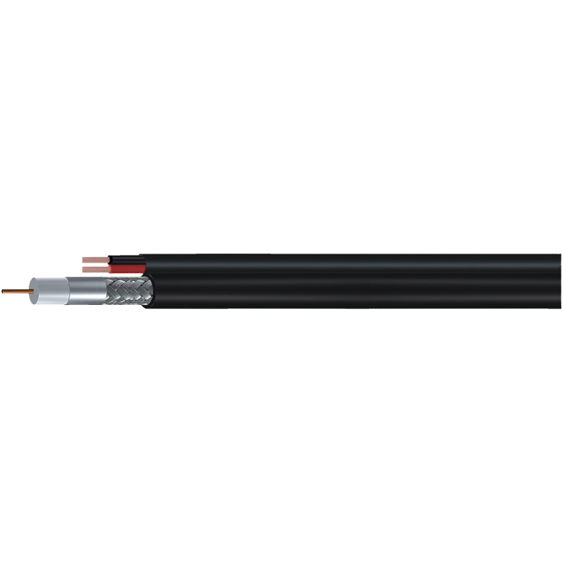 RG59 with Power CCTV Camera Coaxial CableThis hybrid cable carries both video and power for CCTV installations. The manufacturer lists UL, ETL, CE, and RoHS certifications, and the surrounding text treats the diagram as an installation guide for moisture and bend handling.View Product →
Installation Mistakes the Diagram Can Prevent
The drawing also works as a set of installation instructions. Read the jacket as a warning about moisture, read the braid as a warning about connector prep, and read the dielectric as a reminder to avoid sharp bends.
- Strip the outer jacket carefully and avoid cutting into the braid. A single broken strand can turn the shield into a high-impedance path.
- Fold the braid back uniformly over the jacket before installing a compression connector. Uneven folds create gaps that leak signal.
- Expose only the length of dielectric specified by the connector. Leaving extra dielectric exposed changes the impedance at the connection point.
Bend radius. In the diagram, the dielectric has a thickness for a reason. If you bend the cable below its rated radius, the center conductor moves off-center, the local impedance changes, and insertion loss rises.
Water is the quiet killer. Even a small tear in the jacket can let moisture wick along the braid. Once the dielectric absorbs water, attenuation increases and the cable often needs replacement.
The diagram is the cable’s handshake. Once you recognise how the four concentric layers interact, the difference between a good product and a marginal one becomes visible without opening a datasheet. Look at the center conductor, look at the dielectric, look at the shield, and match them to the distance, frequency, and noise of your project. Do that, and a simple cross-section drawing can carry you through the whole installation.