Capacitance in a Coaxial Cable: The Spec That Shapes Signal Quality
A single coaxial cable is more than copper and foam. The capacitance measured between its inner conductor and shield controls bandwidth, phase delay, amplifier loading, and how far a signal can travel before it falls below an acceptable level.
When you open a coax datasheet, capacitance per metre usually sits a few lines below impedance and attenuation. It is also the number most often quoted in specification debates. The usual rule—lower is better—holds true for many video and data paths, but it is not a universal truth. Capacitance interacts with system impedance, cable length and the frequencies you plan to carry. Understand that interaction, and a capacitance figure becomes a reliable design tool rather than a marketing talking point.
What Coaxial Cable Capacitance Actually Represents
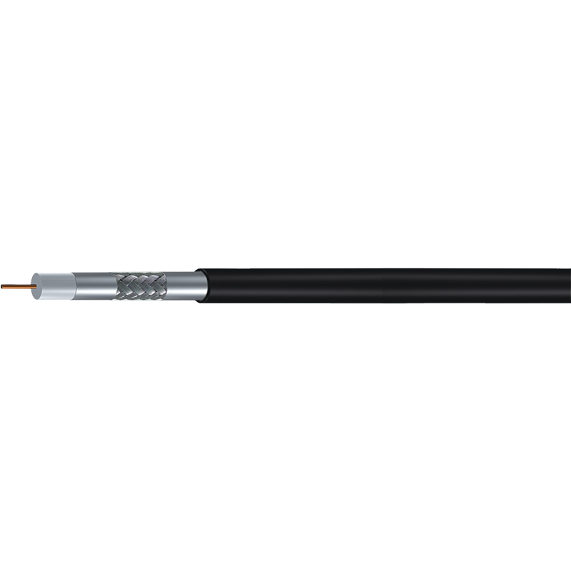
A coaxial cable is, by construction, a capacitor. The centre conductor and the surrounding shield form two conductive surfaces, and the dielectric between them stores charge uniformly along the run. That distributed charge storage is reported as capacitance per unit length, normally in picofarads per metre (pF/m) or picofarads per foot (pF/ft).
For an ideal coaxial structure, capacitance is expressed as C = 2πε / ln(b/a), where a is the radius of the inner conductor, b is the inner radius of the shield, and ε is the dielectric constant of the insulation. Geometry sets the baseline: a thicker centre conductor relative to the shield reduces capacitance. The dielectric has a stronger effect. A physically foamed polyethylene insulation has a lower dielectric constant than solid polyethylene, which is why foamed cables routinely show lower capacitance than solid versions with the same dimensions.
This also explains why two cables carrying the same RG-6 name can report different capacitance values. The naming convention defines a broad mechanical and electrical family, not the exact recipe of the dielectric. A manufacturer that controls foam density and extrusion tightly delivers consistent capacitance from spool to spool; one that does not produces cable that tests acceptably on paper but behaves unpredictably over distance.
Why Capacitance Matters in Real Signal Paths
The practical impact is easiest to see in baseband video and digital signals. Cable capacitance, combined with source impedance and receiver input resistance, forms a low-pass filter. Higher capacitance per metre lowers the cutoff frequency, which rounds edges, softens analogue pictures and shortens the maximum usable distance. In matched RF transmission, the same capacitance participates in defining characteristic impedance; variation along the cable creates reflections.
- Bandwidth and edge rates: A higher capacitance creates a lower cutoff frequency, which rounds digital edges and softens analogue video. For HD-TVI, AHD and CVI cameras, this directly limits practical cable length.
- Source loading: Transmitters, modulators and camera drivers must charge the cable capacitance. When capacitance is high, the driving stage reaches its current limit sooner and usable distance shrinks.
- Phase delay: Propagation velocity depends on the inductance and capacitance of the line. Higher capacitance means slower propagation, which adds delay on long runs and can matter in distributed timing applications.
- Impedance continuity: Characteristic impedance is the square root of L/C. If capacitance changes along the cable, impedance changes with it, creating reflections at each transition.
Lower capacitance is generally beneficial in analogue video and high-frequency data applications because it preserves high-frequency content. But it is not a rule to apply blindly. A 50 ohm cable designed for RF feeders has a different capacitance from a 75 ohm video cable, and that difference is intentional: it follows from the geometry needed to achieve the correct impedance. Comparing pF/m values across cables of different impedance without context can lead to poor choices.
Typical Capacitance Values for Common Coaxial Cables
To make the numbers practical, here are representative capacitance values for cable families used in CCTV, CATV and RF systems. Treat them as reference ranges rather than exact figures; every manufacturer publishes slightly different numbers depending on insulation and construction.
| Cable family | Impedance | Capacitance (approx.) | Typical use |
|---|---|---|---|
| RG-58 | 50 ohm | ≈95 pF/m (≈29 pF/ft) | Legacy RF, test equipment, short patch runs |
| RG-59 | 75 ohm | ≈53 pF/m (≈16 pF/ft) | CCTV, composite analogue video, short drops |
| RG-6 | 75 ohm | ≈53 pF/m (≈16 pF/ft) | CATV, satellite, HD CCTV, broadband |
| RG-11 | 75 ohm | ≈51 pF/m (≈16 pF/ft) | Long trunk runs, distribution networks |
| RG-213 | 50 ohm | ≈97 pF/m (≈30 pF/ft) | High-power RF, antenna feeders |
The 75 ohm video families sit close to 53 pF/m, but subtle differences exist between models because of dielectric diameter and foam density. Shielding layers—standard, trishield or quadshield—affect immunity and leakage, not capacitance to the same degree. In a short residential run, those differences rarely matter. When runs reach 100 metres or more, the combination of capacitance and shielding becomes decisive. That is when consistent dielectric performance outweighs the nominal number on a table.
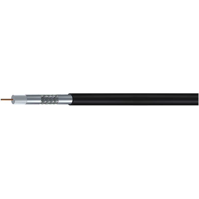
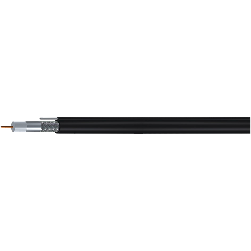
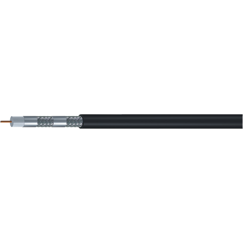
 RG59 Standard Shield 75 Ohm Coaxial CableThis classic 75-ohm cable suits video and security runs. Its stable impedance and moderate capacitance make it practical when evaluating dielectric consistency for longer distances.View Product →
How to Use Capacitance During Cable Selection
A practical sequence for comparing coaxial cables is to fix the system impedance first, then evaluate capacitance, then attenuation, then shielding. If the impedance is wrong, capacitance cannot fix it. If capacitance is unusually high for the product family, expect more signal loss over distance and more demand on the driving circuit.
- Define the distance: Below 50 metres, most RG-59 and RG-6 variants work. Above 100 metres, low capacitance and low attenuation move to the top of the list.
- Know the signal format: Analogue composite video is forgiving. HD-over-coax formats require more bandwidth and benefit from cable with stable low capacitance.
- Check the insulation type: Foamed dielectric and consistent foam density maintain low capacitance and stable impedance. Poorly controlled regrind or recycled insulation can drift.
- Inspect the quality documents: Some suppliers provide actual tested values. Compare capacitance, attenuation and impedance tolerance rather than relying on a single datasheet.
For most video and broadband distribution, a standard-shield or trishield RG-6 balances low capacitance, manageable diameter and proven performance. Our guide to RG6 75-ohm coaxial cable explains where it fits in a system and when another cable family is better.
Low-capacitance RG-6 with good shielding is often the safest choice for longer CCTV runs, especially with HD-TVI or AHD cameras. It keeps the video signal cleaner and leaves more margin for connector losses.
Do not choose a cable solely by outer diameter or price. A low-cost dielectric can show capacitance drift with temperature and flexing, turning an acceptable installation into one with unexplained signal errors or ghosting.
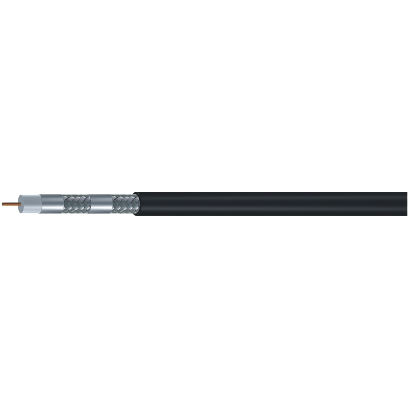
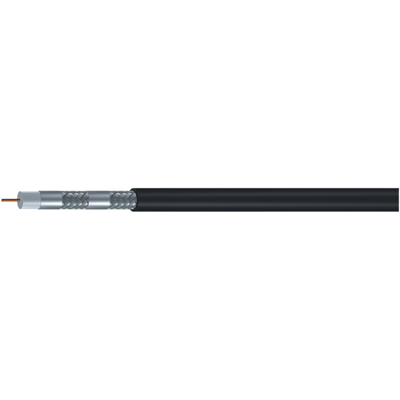
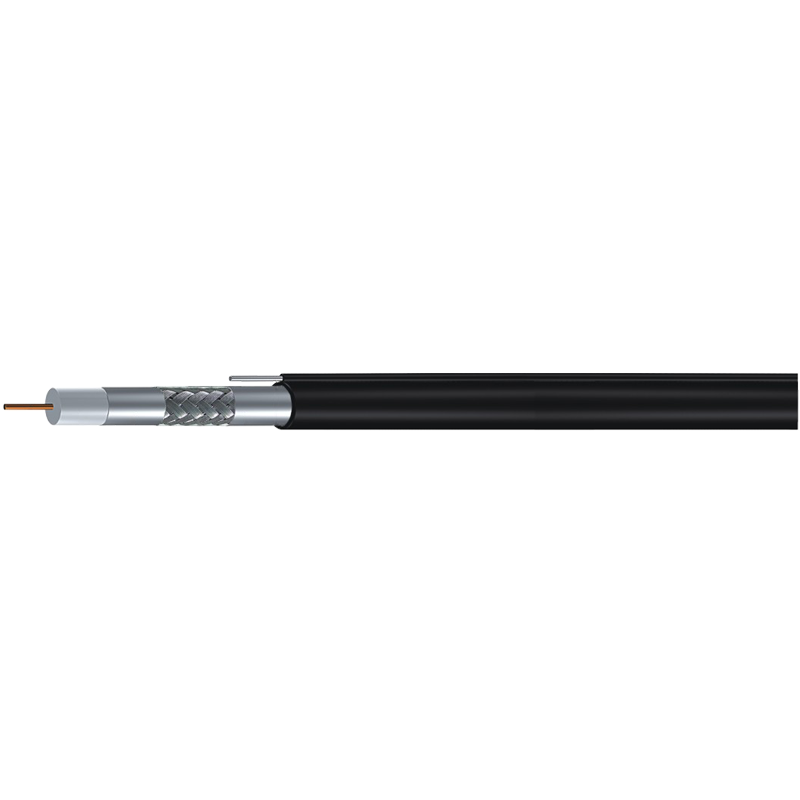
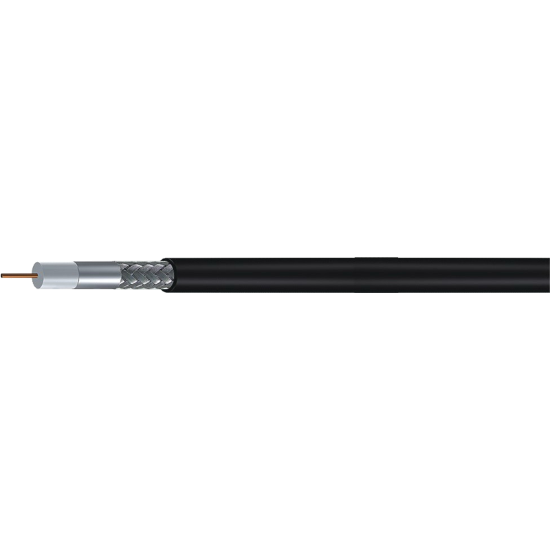
 RG6 Tri-Shield 75 Ohm Coaxial CableA tri-shielded 75-ohm cable with foam dielectric. Its capacitance and shielding matter for batch quality checks, helping avoid signal errors in longer installations.View Product →
Acceptance Testing and Installation Practices
Capacitance is also an acceptance criterion. If a batch measures noticeably higher than the datasheet value, the dielectric may be inconsistent or the geometry may have shifted. A basic LCR meter at 1 kHz, or a cable analyser, will expose batch-to-batch variation before you install hundreds of metres.
Datasheet capacitance is often measured at 1 kHz or 10 kHz. The value is a useful consistency indicator, but it is not a substitute for insertion-loss testing at the operating frequency.
“The capacitance figure on a datasheet is the fingerprint of how carefully the dielectric was made. When it drifts, attenuation and impedance drift with it.”
During installation, treat capacitance as something you can damage. Sharp bends change the conductor spacing locally, increasing capacitance and creating an impedance discontinuity. Pulling tension stretches the dielectric and alters dimensions; follow the manufacturer’s minimum bend radius and maximum pull tension. Use connectors that preserve the dielectric geometry and terminate carefully.
These installation details matter more on long horizontal runs than on short patch cords. If signal loss is your main concern, reviewing the recommended installation techniques for minimizing signal loss before pulling cable is time well spent.
Do not mix cable families with different capacitance values on the same link. Even if the connectors match, a transition from 53 pF/m cable to a higher-capacitance cable creates a local impedance mismatch and reflected signal. Keep each run electrically uniform.
For long feeder or trunk sections, a thicker 75 ohm design such as RG-11 reduces attenuation and keeps capacitance low over distances where RG-6 would be marginal.
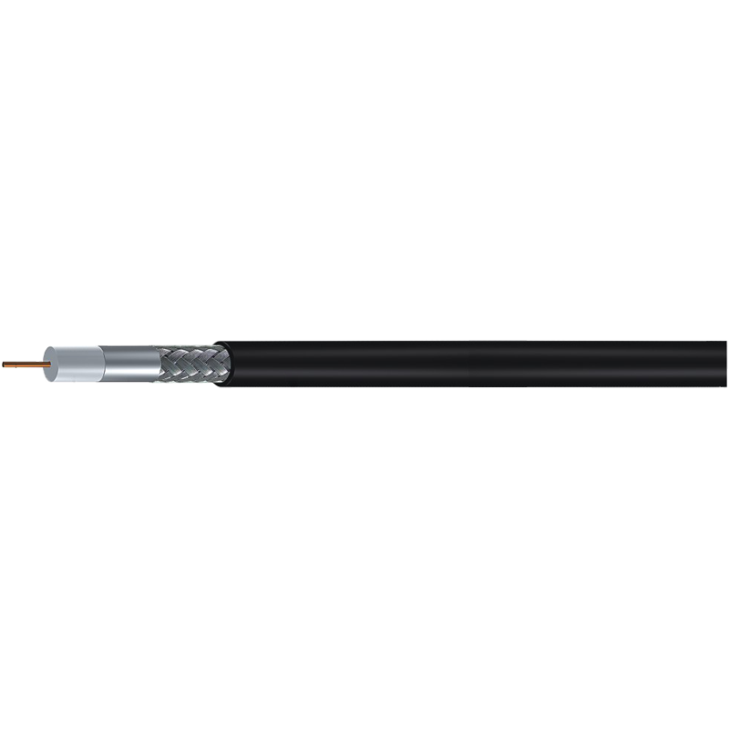
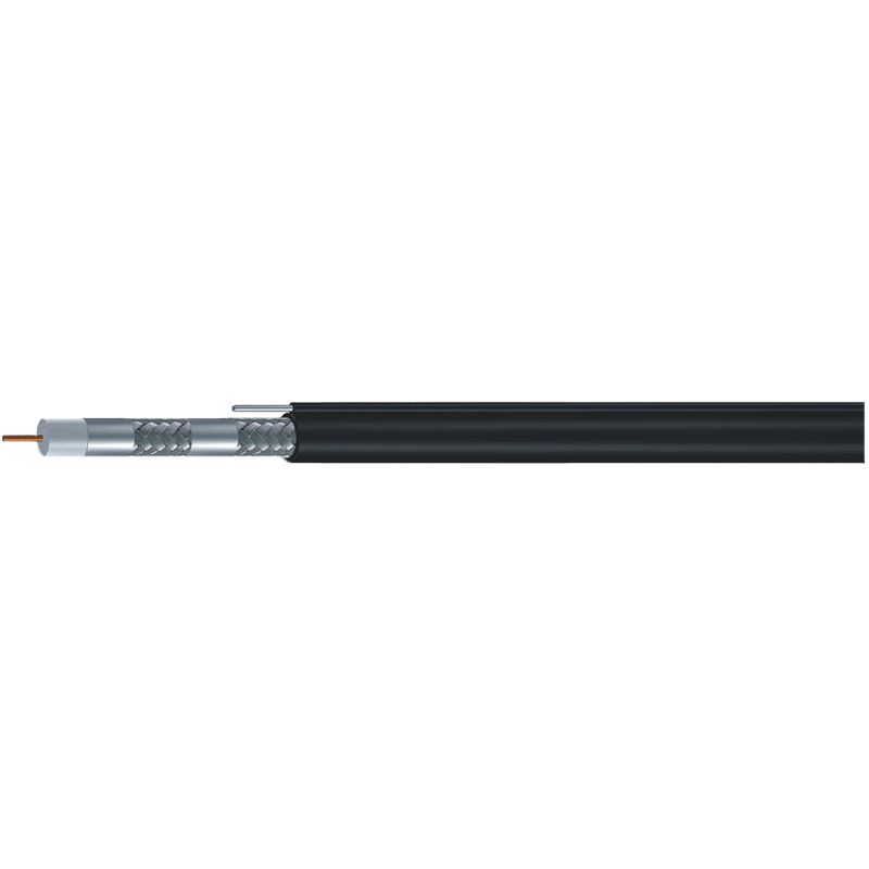
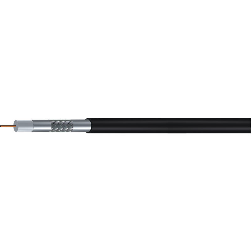
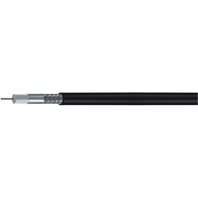 RG11 Standard Shield 75 Ohm Coaxial CableA thicker 75-ohm cable offering lower attenuation over long runs. Ideal for feeder or trunk sections where RG-6 would be marginal and capacitance stability is critical.View Product →
A Balanced View of Coaxial Cable Capacitance
Coaxial cable capacitance is not a defect, nor a standalone performance score. It reflects the cable’s geometry and dielectric quality, and it becomes harmful only when it is mismatched with the application. For video and broadband systems, stable low capacitance is a sign of well-controlled production. For RF systems with a deliberate 50 ohm impedance, a different capacitance range is normal. The right approach is to make capacitance one of several specifications that must work together.
When comparing suppliers, ask how capacitance is controlled in production, not just what number is printed in the brochure. Consistent dielectric foam density, certified materials and documented test data are the reasons two identical-looking cables can perform very differently in the field.