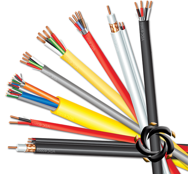
Cable Selection Field Guide
CATV Coaxial Cable: Choosing the Right 75-ohm Line for the Job
The cable behind the wall decides whether a cable television installation delivers clean pictures or a lifetime of interference.
Walk into a CATV project that keeps failing and you will find the same pattern: amplifiers were set correctly, headend levels were tuned, and still the subscriber signal is poor. The drop cable was treated as a commodity. Every meter of coaxial cable contributes attenuation, and every gap in shielding invites interference. The cables that last are not necessarily the expensive ones; they are the ones selected for the distance, the frequency plan, and the radio environment of the building.
What Makes a Coaxial Cable a CATV Cable
CATV began as Community Antenna Television: one strong antenna serving a whole community through a shared network of amplifiers and cables. The architecture has not changed. Today the same 75-ohm network also carries broadband internet over DOCSIS, so the cable transports television and data spectrum at the same time.
Info. Modern frequency plans already reach toward 1.2 GHz. A cable chosen only for an old analog channel plan will be out of spec for the digital services running on the same line.
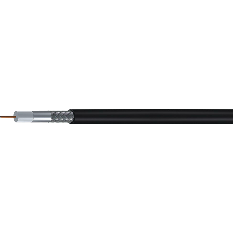
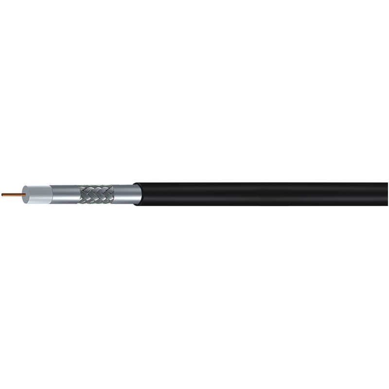
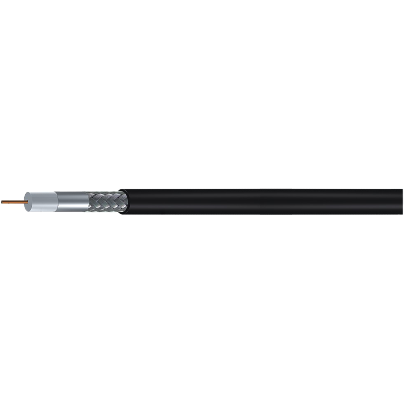
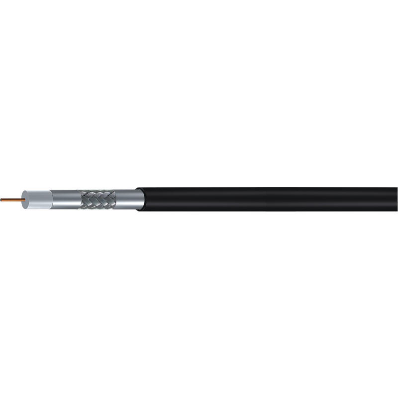
A CATV coaxial cable is a transmission line with a precise geometry. Four functional layers carry the signal and protect it:
- Center conductor — copper or copper-clad steel, carries the signal.
- Dielectric — foam insulation that holds the conductor on the cable’s axis.
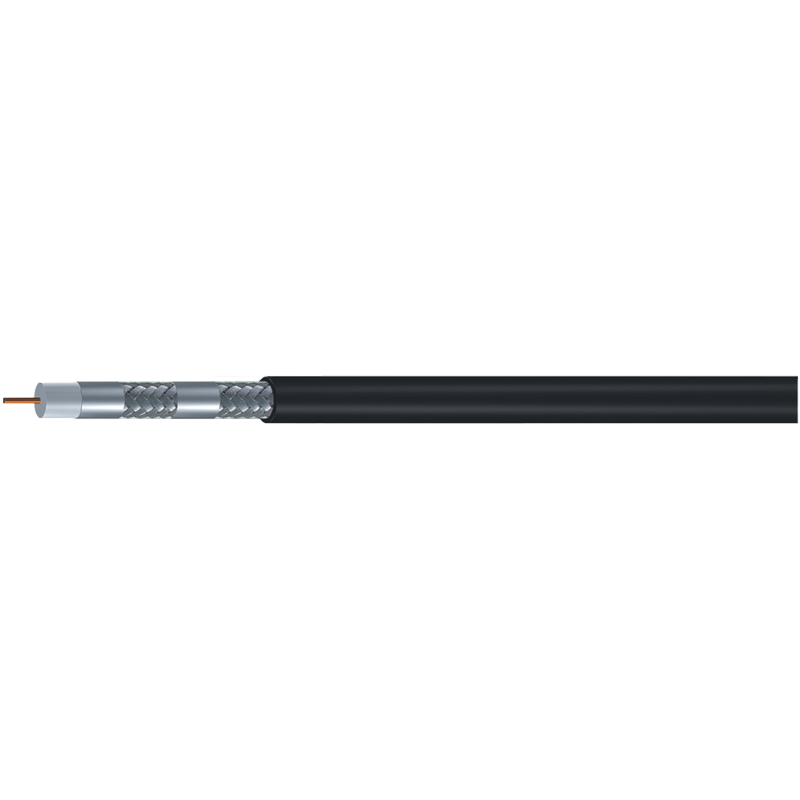
- Shield — foil and braid layers that keep the signal inside the cable.
- Jacket — protection against moisture, abrasion, and sunlight.
Conductor diameter and dielectric dimension together set the impedance. As long as the geometry stays constant, signals travel with minimal reflection; where geometry changes, part of the signal reflects back toward the source. Selection and termination quality are the two ways an installer keeps those reflections negligible.
Every decibel of attenuation you save at the beginning of a run is a decibel you never need to recover with an amplifier later.
Why 75 Ohms Is the Non-Negotiable Standard
Cable television equipment was standardized around 75-ohm impedance decades ago, and the standard persists because it suits the frequencies used by television and broadband. Impedance matching determines how much energy transfers from the tap to the receiver. If cable and connectors are not both 75 ohms, part of the signal bounces at the junction and arrives again as a delayed echo.
This is why 50-ohm cables such as RG58 and the DFB series, built for wireless and radio work, must not be used in a CATV drop. They are good cables, but they are built for a different impedance. Splicing one into a 75-ohm line creates a mismatch that produces ghosting on legacy video and error bursts on digital services.
Warning. Do not substitute cable by appearance. RG58/U looks similar to RG59 at a glance, but RG58 is 50 ohms. Check the printed jacket before terminating a long run; re-terminating a corridor because of a wrong spool is expensive and avoidable.
Within the 75-ohm world the same principle applies at a smaller scale. Every connector, splice, and barrel adds a small impedance variation; the goal is a reflection level low enough that the modem’s error correction never has to work continuously.
RG6, RG59, and RG11: What the Designations Actually Tell You
The RG prefix comes from an old military catalog and is not a complete specification by itself. In practice the three common 75-ohm families map to distinct sizes and performance bands, and serious manufacturers publish the numbers that define each variant.
RG59: the short, flexible link
RG59 is the thinnest of the three, about 6 mm overall, and the easiest to bend around existing construction. Attenuation climbs quickly at higher frequencies, so it suits short video and legacy links rather than modern broadband drops.
RG6: the universal drop cable
RG6 is the default choice for contemporary CATV work. The thicker dielectric and center conductor give meaningfully lower attenuation than RG59 through the 1 GHz-plus range while keeping enough flexibility for walls and risers. Teams planning large upgrades should take a closer look at RG6 75-ohm coaxial cable before committing to a single variant for an entire building.
RG11: the distance specialist
RG11 has the thickest conductor and dielectric, around 10 mm, and the lowest attenuation per meter of the three. The cost is stiffness: RG11 is harder to pull and needs connectors and bend radii that respect its diameter. Use it where the distance budget demands it: long feeder drops, risers, and paths to distant buildings.
| Property | RG59 | RG6 | RG11 |
|---|---|---|---|
| Typical overall diameter | 6.1 mm | 6.9 mm | 10.3 mm |
| Attenuation per meter at high frequencies | Highest | Medium | Lowest |
| Flexibility | Easiest to route | Balanced | Stiff |
| Common CATV role | Short patch and legacy runs | Universal subscriber drop | Long feeders and risers |
| Termination care | Standard F connector | Standard F connector | RG11-sized connector, larger bend radius |
For most projects RG6 is the correct compromise. Choosing RG11 for every run adds cost without reducing attenuation where it was already acceptable; downgrading to RG59 on a long run costs more in rework later.
Shielding: Standard, Trishield, or Quadshield?
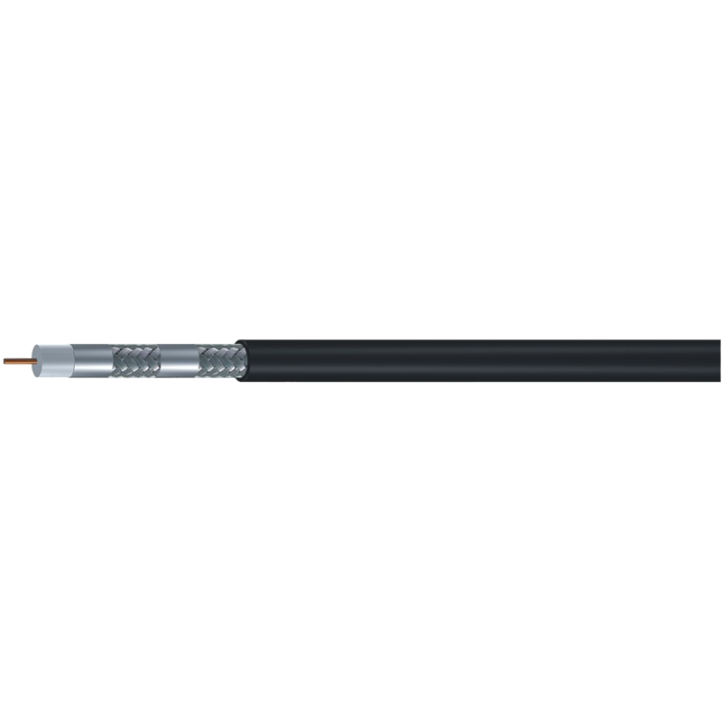
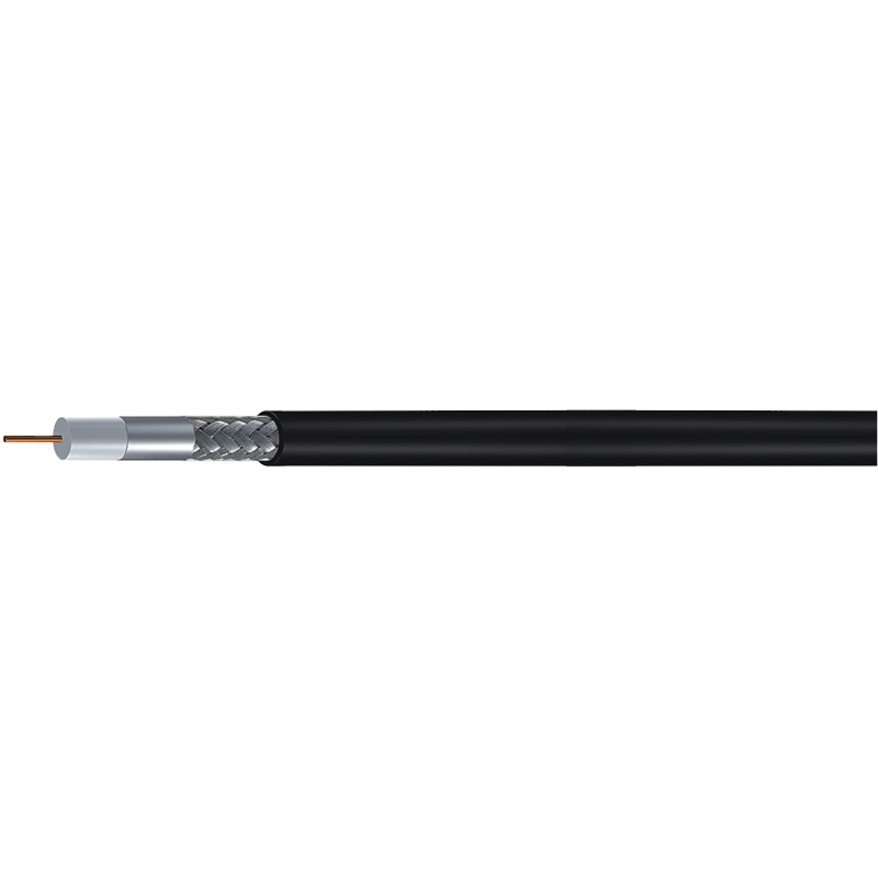
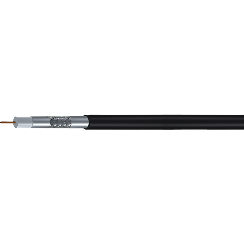
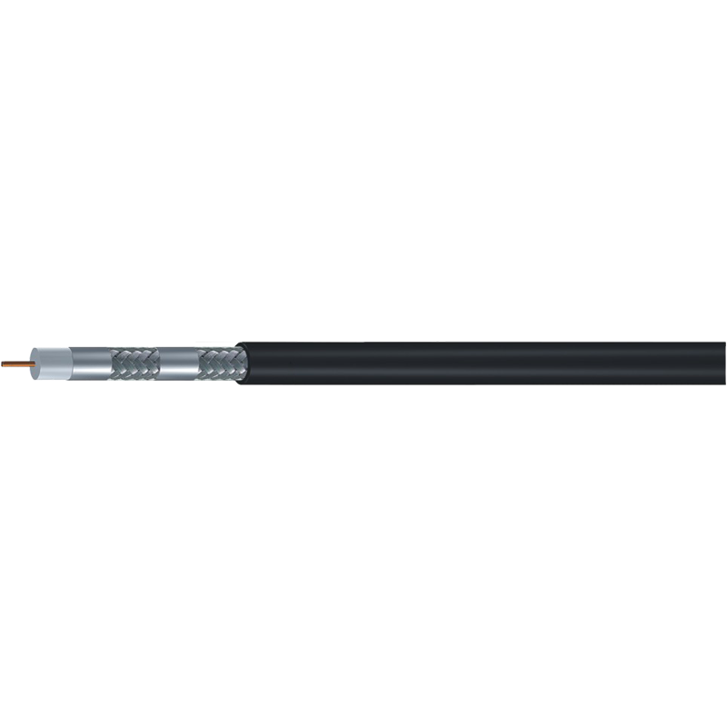
Shielding does two jobs: it keeps external radio energy out of the cable and keeps the cable’s own signal from radiating into nearby equipment. A standard shield usually combines one aluminum foil and one braid. Trishield adds a second foil; quadshield adds another foil-braid pair. The result is a measurable gain in isolation, especially in cellular frequency bands where ingress damage is most visible.
Urban sites near 4G and 5G antennas change old assumptions. A drop cable can act as an unintended antenna: when a strong mobile signal meets imperfect shielding or a poor termination, it leaks into the network and lands in the downstream band. Subscribers see intermittent degradation that is hard to reproduce and easy to misdiagnose. Quadshield is the practical answer in dense radio environments.
There is a middle path for interiors with moderate exposure: trishield adds meaningful protection while remaining cost-effective.
Danger. A damaged shield destroys the value of a good cable. Folding the braid unevenly, using a connector made for a different diameter, or over-crimping until the dielectric deforms turns a quadshield drop into a noise collector. RG6 and RG11 connectors are not interchangeable.
Messenger Cable for Aerial and Long Spans
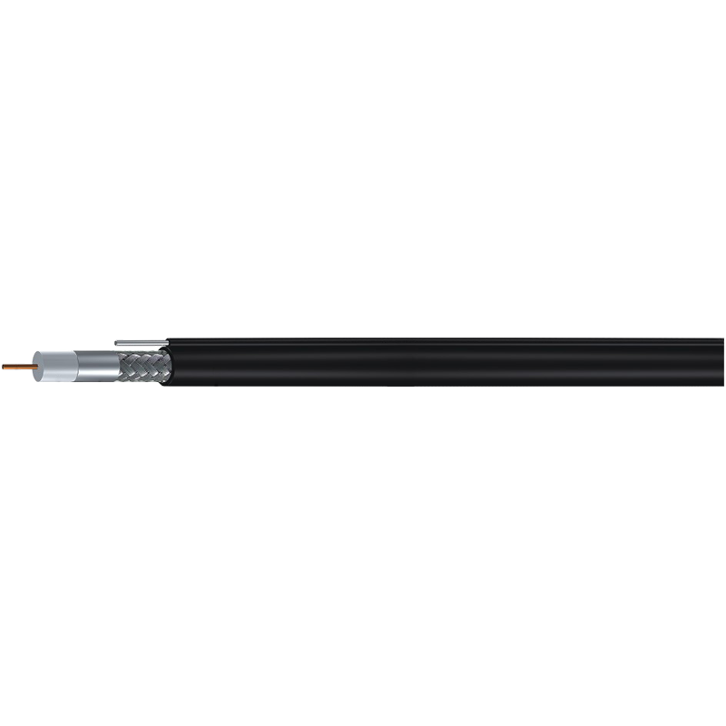
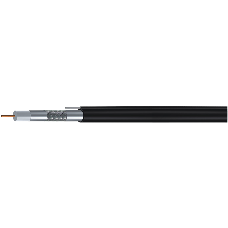
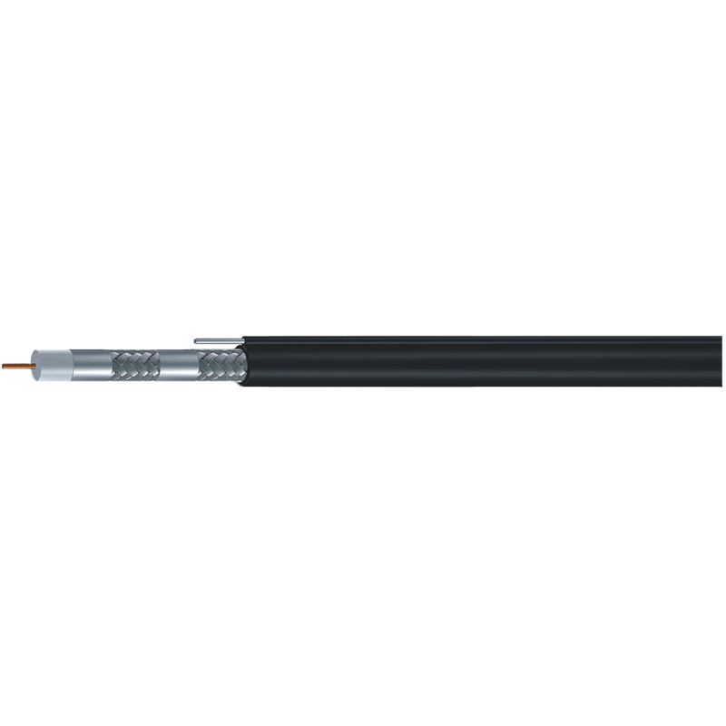
When coaxial cable crosses a street or runs from a pole to a building, tensile strength matters as much as shielding. Messenger cable integrates a steel wire along the cable body so the line supports its own weight between attachment points without separate lashing. On a datasheet, the words “with messenger” identify a variant rated for self-supporting aerial installation.
The electrical rules do not change for aerial paths: the cable still needs the right impedance and shield structure; the messenger only solves the mechanical problem. For a long final span from pole to house, a messenger variant with the same performance as a high-grade drop is the correct engineering answer.
For the larger arteries that feed entire neighborhoods, operators move up to a trunk-class line; knowing how a trunk coaxial cable is constructed clarifies the relationship between a subscriber drop and the distribution design that feeds it.
A Working Selection Process for a CATV Drop
Standardize the decision and allow exceptions only when the situation requires them. The sequence below works for a single subscriber drop and for a multi-building rollout:
- Confirm 75-ohm impedance on the datasheet before considering anything else.
- Measure the full path length, including risers, service loops, and cable trays.
- Select the RG family from the distance and attenuation budget: RG6 for most drops, RG11 when RG6 exceeds its budget.
- Choose the shield structure from the electromagnetic environment rather than from habit.
- Select a messenger variant for any self-supporting aerial section.
- Specify compression-type F connectors sized to the exact cable and discard any connector that was pulled, reused, or has worn threads.
Success. The cheapest validation is a sample test: terminate a 10-meter piece with the exact connectors planned for the job and measure it at the frequencies the network actually uses. If the sample meets attenuation and return-loss targets, the production run will almost certainly perform the same.
The discipline that separates good CATV installations from reactive ones is documentation. Record which cable families were installed, which spools were used, and which connectors were fitted. When a fault appears, the records narrow the cause to a component instead of forcing the crew to inspect every meter.
The Bottom Line
CATV coaxial cable selection is really three questions. What impedance? Almost always 75 ohms. What size class? RG6 for standard drops, RG11 for long paths, RG59 only for short legacy links. What shielding? The best shield the radio environment justifies, with quadshield as the default in crowded signal areas and messenger variants wherever the cable is airborne.
Termination quality and procurement discipline decide whether that selection survives contact with the real world. Request attenuation data at the frequencies your network uses, confirm the certifications your destination market requires, and pull a sample from every production batch before installation begins. A great cable spec is the one component you never have to think about again.