Cable Selection / Technical Guide
Coaxial Cable Specifications, Read Like a Story
Impedance, shielding, attenuation, and jacket ratings are not isolated numbers. They are the language a cable uses to tell you where it belongs.
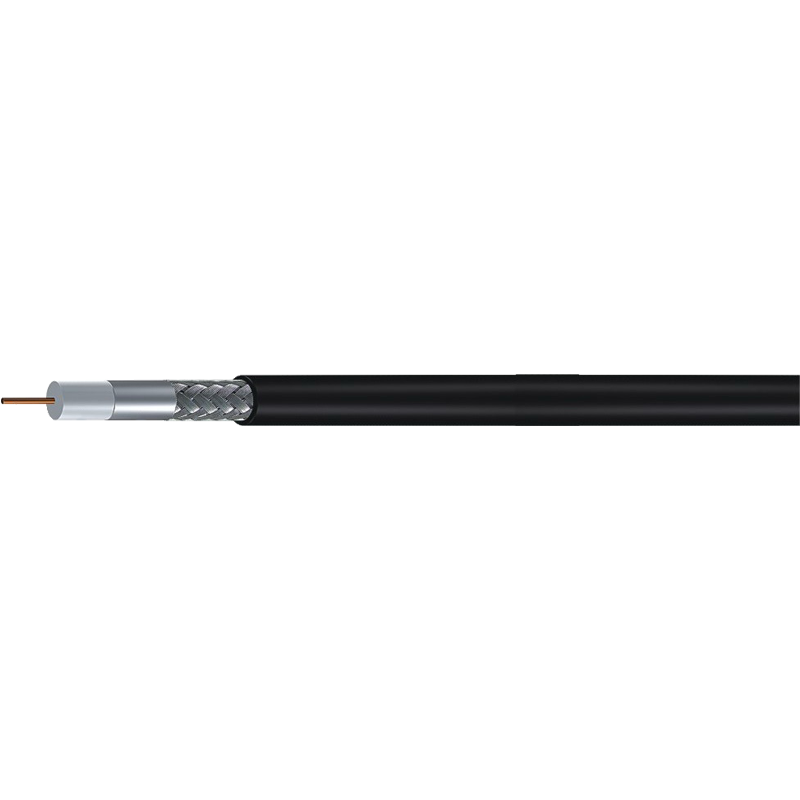
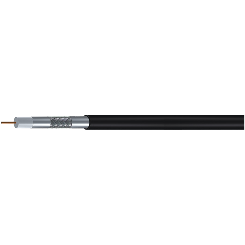
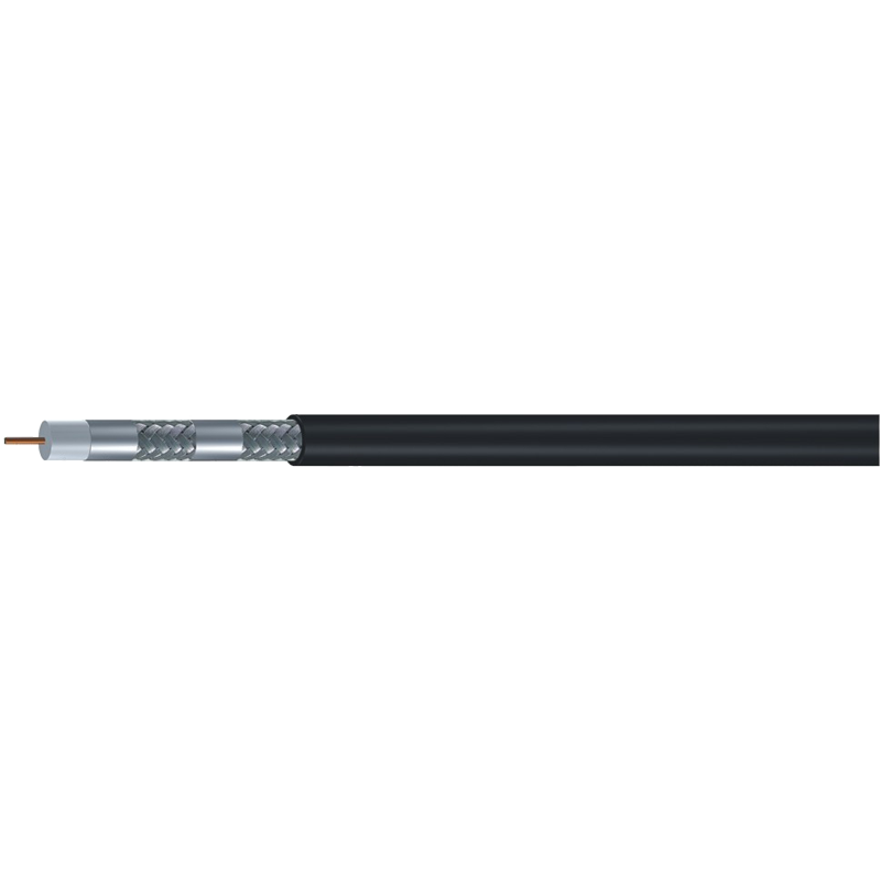
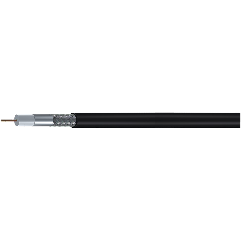
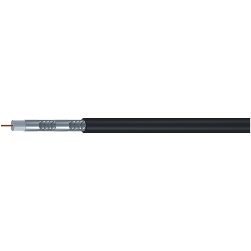
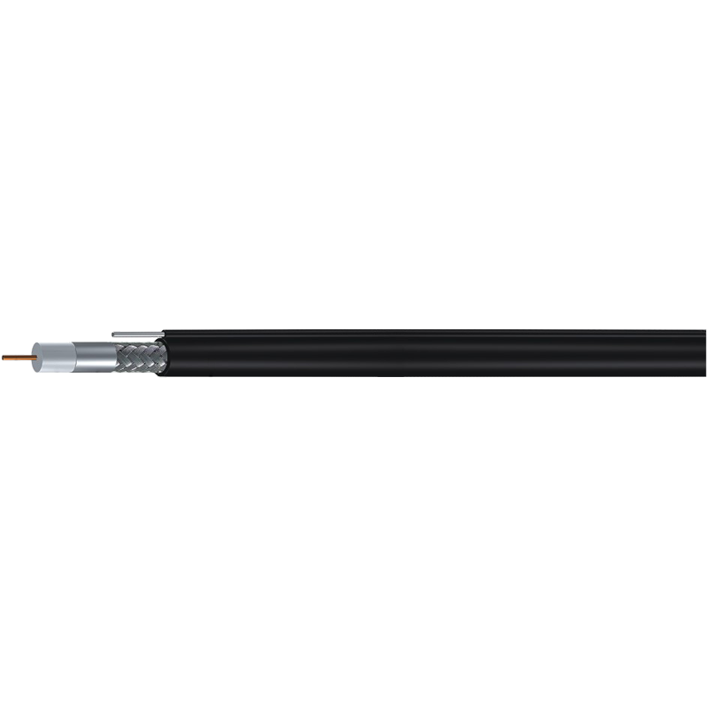
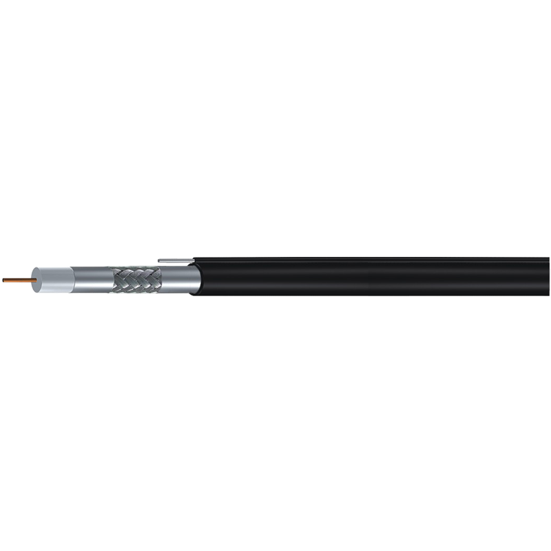
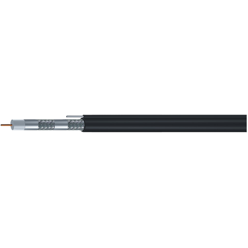
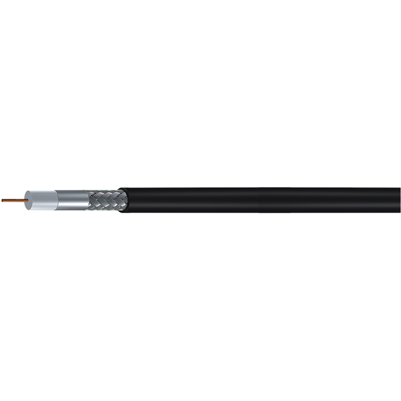
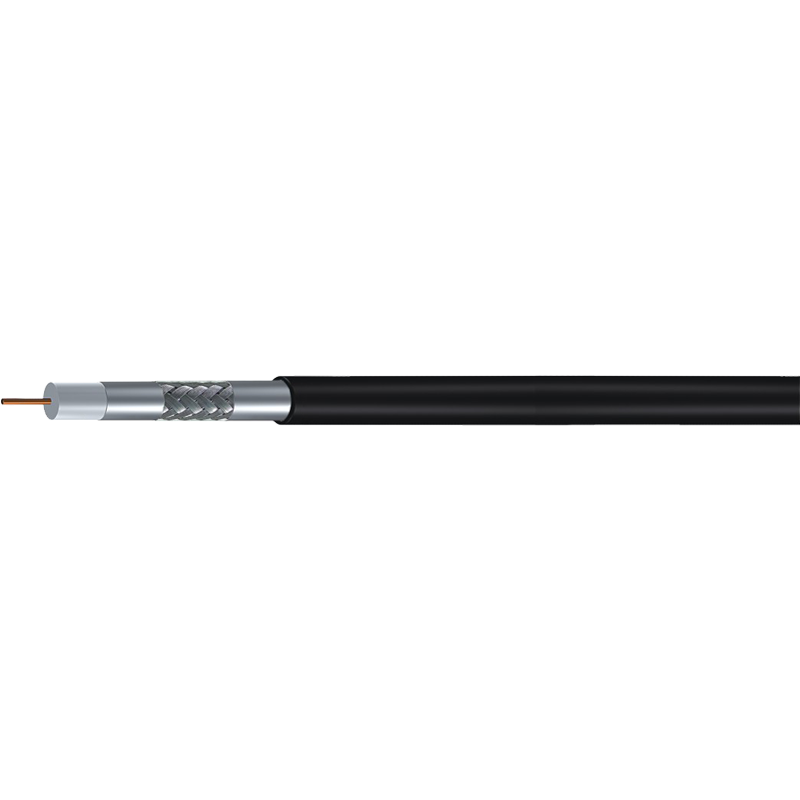
A coaxial cable looks simple from the outside: a round jacket, a connector, a printed part number. Inside, four layers are doing quiet, precise work. The center conductor carries the signal. The dielectric holds it at a fixed distance. The shield keeps outside energy out and the signal in. The jacket protects the whole assembly from weather, abrasion, and the ordinary accidents of an installation.
Coaxial cable specifications translate that physical stack into decisions. They tell you whether a cable will carry a satellite feed across a garden, keep a camera image clean in an industrial yard, or hold a stable RF link inside an equipment room. The numbers matter, but they matter in context. A specification sheet is not a scorecard; it is a map of intended behavior.
A specification is not a marketing badge. It is a promise about behavior at a given frequency, over a given distance, in a given environment.
The most useful specification is the one that answers a real installation question: will this cable still perform at the end of the run, after the connector, in the weather it will actually meet?
Impedance Is the First Fork in the Road
Characteristic impedance is the first specification to settle, because it shapes the rest of the system. In coaxial cable, 75 ohm is the video and broadcast standard: satellite television, CATV, DTV, MATV, and CCTV video. 50 ohm is the RF and wireless standard: antenna feeders, LTE, two-way radio, test equipment, and low-power RF links. The two families are not interchangeable. A 75 ohm cable on a 50 ohm radio path, or the reverse, creates reflections and wasted signal.
Impedance is not the same as resistance. It is a property of the cable's geometry and dielectric, and it stays relatively stable across frequency. What changes is loss. So once impedance is fixed, the real work begins: choosing a cable size, shield, and jacket that keep loss within budget for the actual run.
 50 Ohm Low-Loss RF Coaxial Cable RangeBrowse 50 Ohm low-loss coaxial cable families, including 4D-FB to 12D-FB, RG174, RG58, RG213, LMR200 and LMR400, for signal and high-power applications.View Product →
On the 75 ohm side, the same logic applies. RG6, RG11, and RG59 share an impedance, but they are not the same cable. Diameter, conductor, shield coverage, and jacket compound decide where each one belongs.
The Four Layers Behind Every Number
Center conductor
Every specification starts with the center conductor. Solid copper offers the lowest resistance. Copper-clad steel adds tensile strength for overhead runs. Stranded conductors improve flexibility. The choice affects attenuation, handling, and connector termination. In long drops, the conductor diameter is often the quiet reason one cable outperforms another.
Dielectric
Dielectric material sets velocity of propagation and capacitance. Solid polyethylene is common and economical. Foamed polyethylene lowers weight and loss, which is why it appears in many broadband and satellite designs. The dielectric also fixes the distance between conductor and shield, so its concentricity matters.
Shield
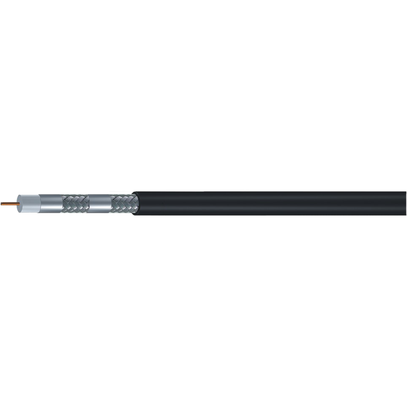
Shielding is where many catalogs get interesting. A standard shield may use a foil and a braid. Tri-shield adds layers for better coverage. Quad-shield pushes isolation further. More shield can mean better rejection of interference, but it also adds stiffness and cost. The right answer depends on the noise environment and the installation path.
Jacket
Jacket compound is the quiet specification. PVC is flexible and common indoors. Polyethylene suits outdoor sunlight and moisture. LSZH compounds reduce smoke and halogen content in enclosed public spaces. The jacket does not improve signal quality, but it decides whether the cable survives the site.
| Family | Impedance | Typical role | Shielding commonly available | Specification to verify |
|---|---|---|---|---|
| RG6 | 75 Ω | Satellite, CATV, DTV, set-top feeds | Standard, tri-shield, quad-shield; messenger versions | Attenuation at highest channel; conductor material; jacket UV rating |
| RG11 | 75 Ω | Longer drops, trunk and distribution | Standard, tri-shield, quad-shield; messenger versions | Bend radius; tensile strength; attenuation per 100 m |
| RG59 | 75 Ω | Short CCTV and legacy video runs | Standard, tri-shield; with power | Shielding coverage; flexibility; connector fit |
| RG58 | 50 Ω | Short RF, test, low-power wireless | Single or double braid | Loss at frequency; cable diameter; connector type |
| LMR200 / LMR400 | 50 Ω | Antenna feeders, LTE, wireless | Foil plus braid | Flexibility versus loss; bend radius; connector compatibility |
| Trunk 500 / 540 | 75 Ω | Headend, backbone, outdoor distribution | Bonded foil plus braid; messenger versions | Hardline handling; attenuation; grounding |
Reading a Datasheet Without Getting Lost
Attenuation is the headline loss figure, usually stated in dB per 100 feet or 100 meters at specific frequencies. Always read the frequency column. A cable that looks excellent at 50 MHz may be ordinary at 1 GHz. For satellite and CATV work, check loss at the highest channel in the plan, not at the lowest.
Velocity of propagation, often shown as a percentage, describes how fast the signal travels in the cable compared with free space. It matters for timing, phase, and length calculations. Capacitance, usually in pF per foot or meter, is another way to see the dielectric's behavior. Return loss and structural return loss describe how well the cable maintains its impedance; poor values show up as reflections and standing waves.
Info
A specification is frequency-dependent. If a datasheet gives a single attenuation number without a frequency, ask for the full sweep.
Temperature rating, bend radius, tensile strength, and flame or CPR classification are not signal specifications, but they decide whether the cable can be installed legally and safely. In outdoor or riser work, these are often the first gate, not the last.
Match the Cable to the Job, Not the Catalog Page
Satellite, CATV, and DTV
75 ohm RG6 is the familiar workhorse for satellite receivers, cable set-top boxes, and in-home distribution. Tri-shield and quad-shield versions improve isolation where many cables share a bundle. Messenger versions add a support wire for aerial spans. RG11 is the choice when the run is longer or the loss budget is tight; its larger conductor buys margin at the cost of stiffness.
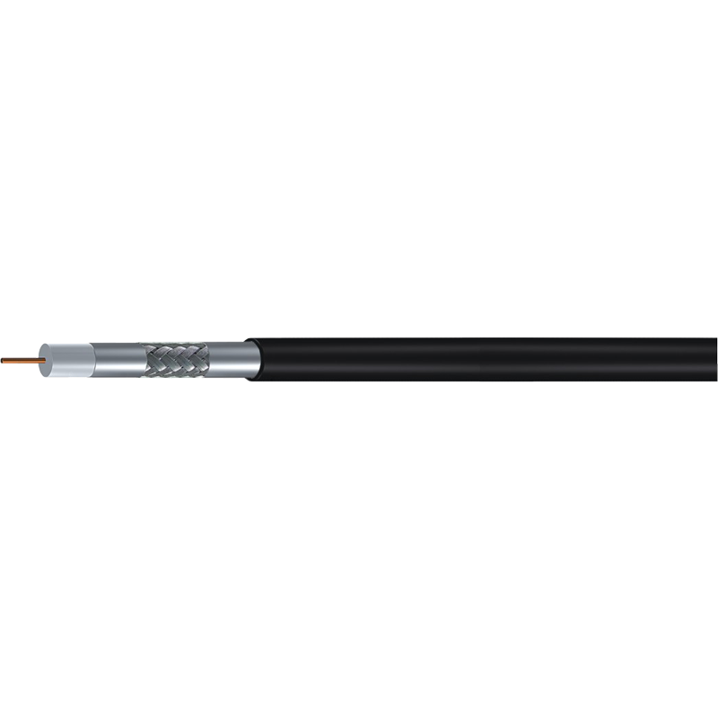 RG6 Tri-Shield 75 Ohm Coaxial CableTri-shield RG6 cable for satellite, CATV and distribution runs, with foil-braid-foil screening and PVC or PE jacket options.View Product →
For a satellite or antenna feed, the cable must also tolerate weather and repeated handling. A UV-stable jacket and a connector system rated for outdoor use are as important as the shield count.
CCTV and powered cameras
CCTV video is still a 75 ohm world, even when the camera is digital. RG59 remains common for short, flexible runs. RG6 gives lower loss on longer runs. Composite constructions add a power pair, so one jacket carries video and low-voltage power to the camera. That saves a separate cable pull, but it also means checking voltage drop and conductor size.
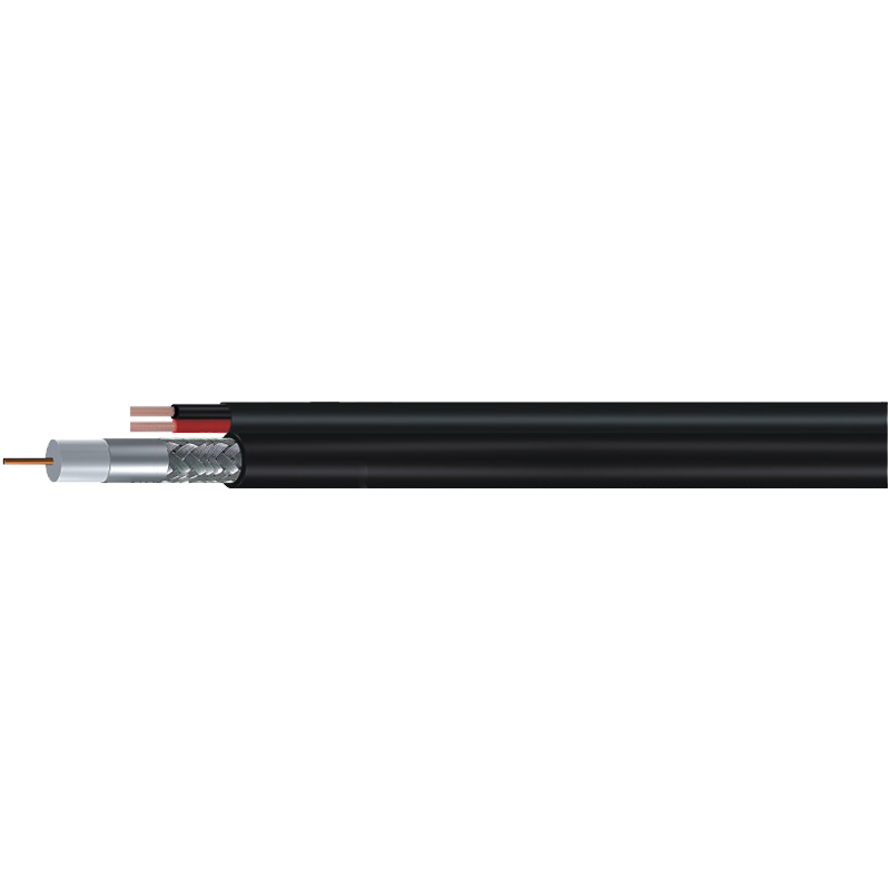 RG6 Coaxial Cable With Integrated Power PairCombined RG6 video and power cable for CCTV installations, reducing separate cable pulls while supporting camera video and low-voltage power runs.View Product →
Powered CCTV cable is convenient, but it is not a substitute for electrical design. Confirm the camera's current draw, the power supply voltage, and the distance before committing to a composite reel.
Wireless, LTE, and RF
50 ohm cables such as RG58, LMR200, and LMR400 serve short RF jumpers and antenna feeders. The trade-off is simple: larger diameter and better shielding lower loss, but reduce flexibility and raise connector cost. For long outdoor feeders, loss at the operating frequency is the number to watch.
Warning
Do not solve a loss problem by changing impedance. Match the cable to the radio or video system first, then choose the largest practical diameter and the shield that suits the environment.
If you are still weighing shield count, jacket material, or connector style, this guide to choosing coaxial cable walks through the practical trade-offs without turning the decision into a catalog exercise.
A Practical Selection Checklist
A good selection process is less about memorizing part numbers and more about asking the same questions in the same order. If you are comparing suppliers, the team at CommSpace Cable can walk through these points with you and help you match the cable to the real installation.
- Confirm system impedance: 75 ohm for video and broadcast, 50 ohm for RF and wireless.
- Measure the longest run and the highest frequency. Calculate loss at that frequency, not at DC.
- Choose conductor and shield for the environment: solid copper for low loss, copper-clad steel for strength, tri-shield or quad-shield for noisy paths.
- Check jacket and compliance: UV-resistant PE for outdoor work, LSZH or CPR-rated compounds where the code requires them.
- Verify connector compatibility and termination method. A good cable with a poor connector is a short service life.
- Confirm the datasheet includes attenuation, velocity of propagation, capacitance, return loss, bend radius, and temperature rating.
Final Word
The best coaxial cable specification is the one you can explain in plain language. It says what the cable is made of, what it will do at the frequencies you intend to use, and where it should not be used. That is more useful than a long list of model numbers.
At CommSpace Cable, we have spent years manufacturing coaxial cable for satellite, CCTV, CATV, broadband, and wireless applications. The lesson is consistent: start with impedance, read the loss curve, and let the installation environment choose the shield and jacket. When the numbers and the site agree, the cable disappears into the system and does its job quietly.
Success
A specification sheet is a conversation starter. The final decision should include the run length, the frequency plan, the connector, and the environment.