Field Guide · Coaxial Infrastructure
Coaxial Cable Connector Types: A Practical Guide
Knowing the difference between BNC, F-type, N, SMA, TNC, and SMB is the first step toward a signal path that holds up in the field.
Whether you are terminating an RG6 drop for a broadband endpoint, a 59-series cable on a CCTV camera, or an LMR-type feed on a wireless access point, the connector is where system performance is won or lost. Connector families differ in impedance, frequency ceiling, coupling mechanism, and environmental tolerance. Pick the wrong one, and the cable rarely gets the blame — the reflections, corrosion, and intermittent contacts that follow are almost always connector problems. This guide explains what each main coaxial connector type is built for, and how to match it to your cable and installation.
What a Coaxial Connector Does, and Why Impedance Sets the Rules
A coaxial connector has one job: preserve the cable's characteristic impedance through the junction. The cable keeps a constant geometry — center conductor, dielectric, braid, jacket — and the connector repeats that geometry in a mating form. When the geometry changes abruptly, or when a connector of the wrong impedance is used, part of the signal reflects back toward the source. The result: attenuated video, higher bit-error rates, or radio front ends that run warm for no obvious reason.
Two impedance families dominate. The 75-ohm family is built for video distribution: CATV, DTV, satellite IF, CCTV, and trunk systems, using cables like RG6, RG59, and RG11. The 50-ohm family is tuned for RF transmission and instrumentation: RG58, RG213, DFB types, and 50-ohm low-loss RF coaxial cables such as LMR400. A 50-ohm connector will physically fit some 75-ohm cables, but the mismatch adds avoidable return loss to the link. Impedance should be the first filter in connector selection.
Info — Even a short impedance mismatch of 10 ohms can produce a visible ghost or soft focus on an analog video link. On digital signals it reduces the noise margin that keeps the link from dropping.
Six Connector Families at a Glance
Most field work in cable systems touches six connector types. Each has its own coupling style and a preferred impedance range, so the practical choice is usually determined by the cable in the ground and the frequency the system runs at.
| Connector | Impedance | Coupling | Typical frequency range | Primary application |
|---|---|---|---|---|
| BNC | 50 / 75 Ω | Bayonet, quarter-turn | DC – 4 GHz | CCTV, video, test instruments |
| F-type | 75 Ω | Threaded | DC – 1 GHz | CATV, DTV, satellite, broadband |
| N-type | 50 Ω | Threaded | DC – 11 GHz | RF antenna feeds, trunk lines |
| SMA | 50 Ω | Threaded, hex nut | DC – 18 GHz | RF modules, antennas, GPS |
| TNC | 50 Ω | Threaded | DC – 11 GHz | Vibration-resistant RF, LTE |
| SMB | 50 Ω | Push-on | DC – 4 GHz | Dense module and PCB interconnects |
The frequency ceilings in the table reflect practical field-grade performance rather than laboratory limits. Within a family, coupling style and installation environment usually decide the final pick.
BNC: The Default for Video and CCTV
BNC — Bayonet Neil-Concelman — is the most recognizable connector in video work. The quarter-turn bayonet locks fast and holds firmly, which is why CCTV installers favor it: cameras sit on poles, walls, and ceiling corners where tool-less mating saves real time. BNC comes in both 50-ohm and 75-ohm versions, so verify the cable before crimping. CCTV runs normally use 75-ohm RG59 or RG6 combined with 75-ohm BNC connectors, especially when cameras transmit composite or HD-analog modulated video over coax.
A growing segment of the CCTV market uses combined video-and-power cables, where signal and DC power travel in one sheath so the camera needs only one pull from the control room to the lens. That approach works well when the BNC termination keeps the shield continuous and the power pair isolated from the video path — a detail that matters on long building runs, where ground loops are easy to create and expensive to diagnose.
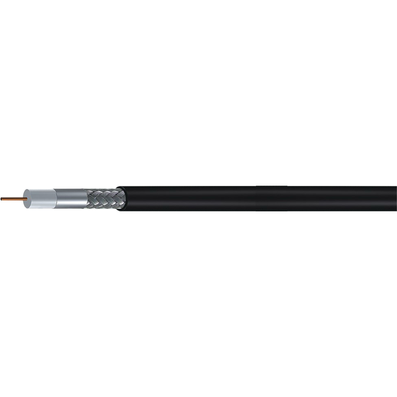
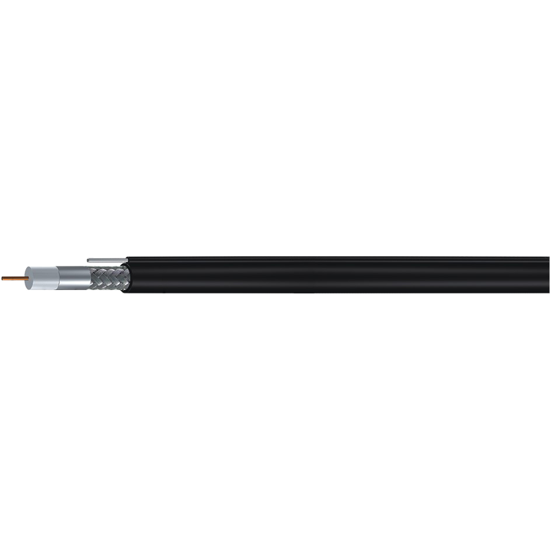
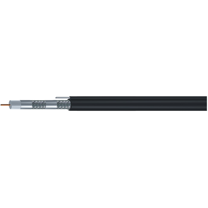
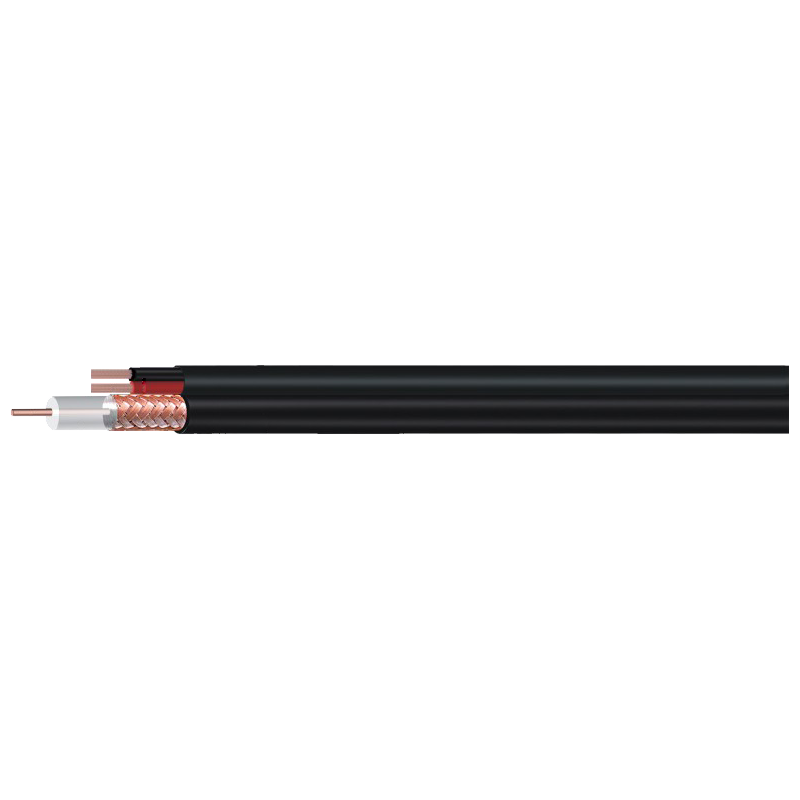 RG59 with Integrated Power Cable for CCTVThis combined coaxial and power cable suits CCTV runs needing one pull, with shielding and isolation to avoid ground loops on long building installations.View Product →
F-Type: The Backbone of Broadband and Satellite
F-type is the default termination for 75-ohm consumer and distribution systems: cable TV, terrestrial DTV, satellite IF, and broadband modems. Its threaded collar holds contact pressure across temperature swings, which is exactly what outside drops and pedestal splitters face. The design uses the cable's own center conductor as the connector pin, removing one part and keeping unit cost predictable — but that makes installation quality critical. A clean, square cut and the correct strip length decide whether the connector meets its specification.
On a typical RG6 75-ohm coaxial cable with tri-shield or quad-shield layers, the connector body must establish reliable contact with the outer braid through the jacket, which is why weather-sealed compression connectors outperform crimp versions on exposed drops. The same 75-ohm F-type world extends to RG11 for longer distribution runs, where a heavier body and a weather boot are standard practice.
Warning — a crimp connector that does not match the exact jacket diameter of a tri-shield cable will crush the dielectric or miss the braid entirely, turning a fresh install into a rework ticket.
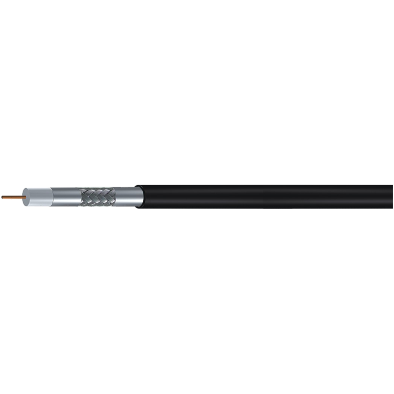
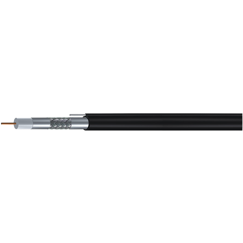
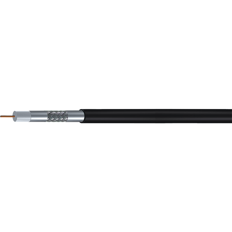
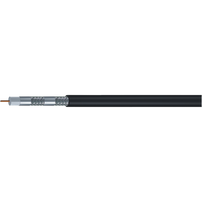
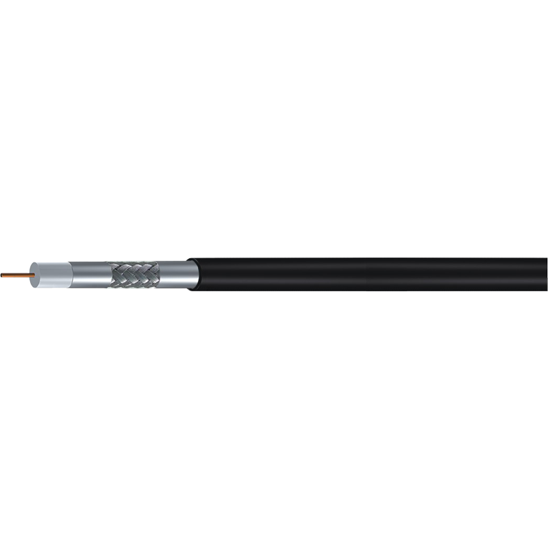 RG6 Tri-Shield 75 Ohm Coaxial CableTri-shield construction handles satellite and broadband signals, but proper connector matching is critical to prevent dielectric crush or missed braid termination.View Product →
N-Type: The Professional RF Workhorse
When the signal has to survive rain, wind, higher transmit power, or frequencies well into the gigahertz range, the Type N connector is the industry workhorse. Its threaded coupling resists vibration, the dielectric support allows repeatable performance to roughly 11 GHz, and the robust center pin handles power levels that would destroy smaller coaxial connectors. N-type is the standard interface on antenna feeders, base-station jumpers, broadcast transmitters, and GPS distribution networks.
In practical RF work, most elusive signal faults trace back to connectors, not cables. A cold solder joint, a braid that was not captured by the clamp, or a mismatched impedance ring reproduces as an intermittent drop long after the cable itself has been tested and cleared.
N-type connectors pair naturally with 50-ohm low-loss cables such as LMR400, RG213, and the DFB series. In trunk and distribution infrastructure, the larger pin and air-loaded dielectric handle high power and low loss, while weatherproof variants add O-rings and captive gaskets for IP-rated enclosures. When a spur line leaves a cabinet and climbs a tower, N-type is the standard field engineers expect to see.
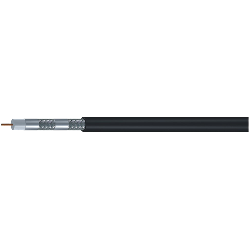
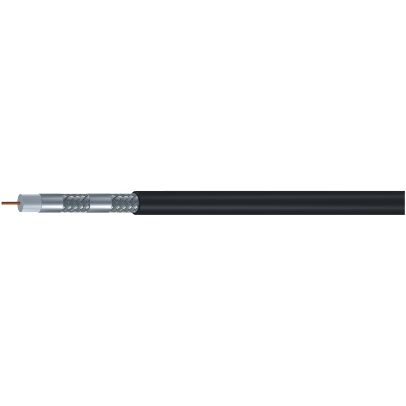
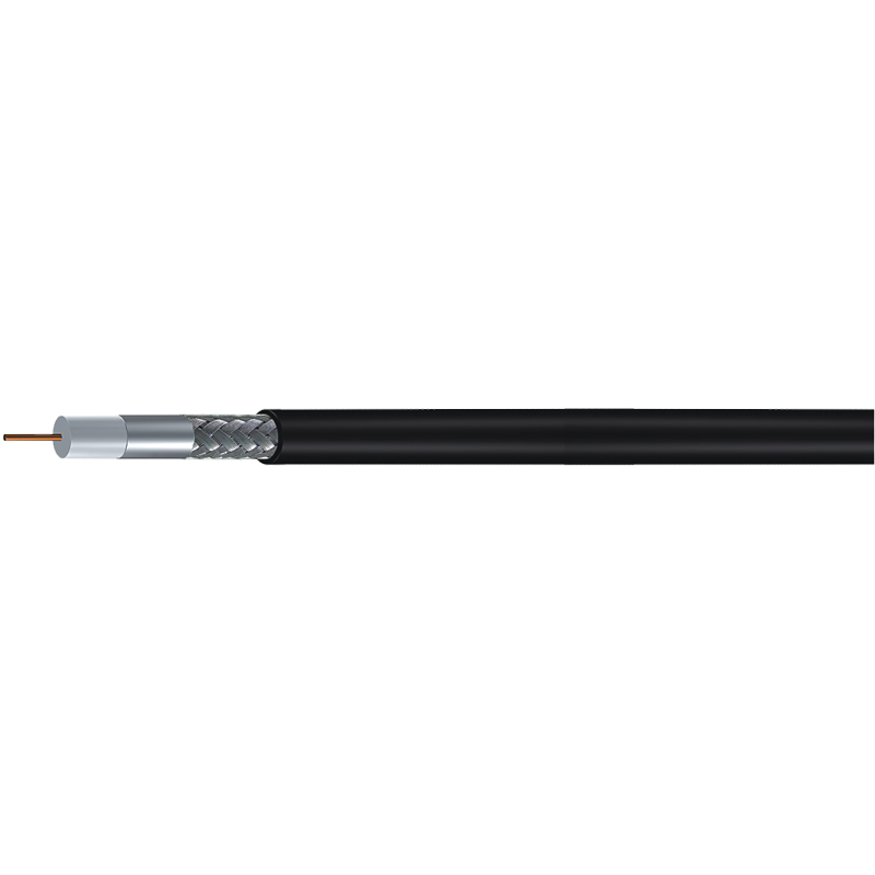
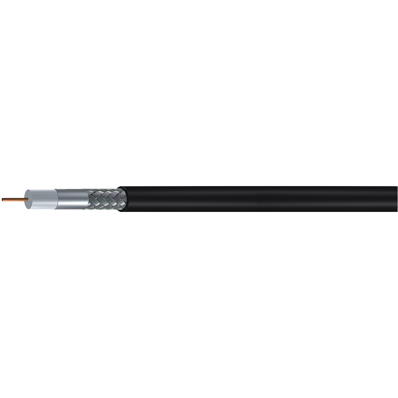 LMR400 50 Ohm Low-Loss Flexible Coaxial CableFlexible low-loss cable designed for antenna feeders and wireless jumpers, pairing well with N-type connectors for high-power and weather-resistant field use.View Product →
SMA, TNC, and SMB: The Compact RF Family
SMA (SubMiniature version A) is the compact threaded connector found on Wi-Fi access-point antennas, RF modules, GPS receivers, and spectrum-analysis adapters. Rated to 18 GHz in standard versions, SMA demands disciplined torquing around 7 in-lb: hand-tight plus a controlled fraction of a turn with a wrench. Reverse-polarity SMA (RP-SMA) changes only the gender arrangement, preserving thread geometry while preventing accidental mating between two commercial antennas; it is common on ISM-band Wi-Fi gear.
TNC (Threaded Neil-Concelman) is the threaded sibling of BNC. It shares BNC's dimensions but adds a threaded coupling, giving vibration resistance and a frequency ceiling around 11 GHz. TNC appears on mobile-radio antennas, LTE infrastructure, and vehicle-mounted radios where shock is constant. SMB, by contrast, is a push-on design for dense internal connections inside RF modules and circuit boards. The lack of threads makes SMB unsuitable for vibration-prone field runs; for those, SMA or TNC is the right call.
Five Checks Before You Order Connectors
- Impedance. Read the cable jacket: 75-ohm cable calls for 75-ohm connectors; 50-ohm cable calls for 50-ohm parts. Mixed paths add avoidable return loss.
- Frequency ceiling. Match the connector rating to the highest frequency in the system, with margin. An 18 GHz SMA is overkill for a 5 GHz Wi-Fi link unless the module already uses SMA.
- Environment. Outdoor and corrosion-prone sites need weatherproof bodies, plated contacts, and sealed interfaces. Indoor commercial runs can use lighter, cheaper versions.
- Coupling style. Frequent disconnects favor BNC's quarter-turn. Permanent outdoor and vibration-sensitive runs favor N-type and TNC threading. SMB push-on is only for confined, stationary gear.
- Cable compatibility. Connector clamps and ferrules are sized for specific cable diameters and shield constructions. A tri-shield RG6 needs the corresponding ferrule, not a standard-shield part.
Success — a well-terminated 75-ohm F-type on an RG6 quad-shield drop, with the right strip length and torque, returns VSWR below 1.5 across the full CATV band and performs without attention for years.
Danger — fitting a 50-ohm SMA on a 75-ohm cable, or forcing an SMB push-on into a vibrating outdoor antenna feed, creates intermittent faults that are expensive to find after the cable is buried or pulled through conduit.
The connector is a small line item in the bill of materials, yet it decides whether the installed cable performs to its rated specification. Start with impedance, verify frequency and environmental limits, then match the coupling style to the access and vibration conditions of the job. When those decisions line up, the rest is craftsmanship: a clean cut, the correct strip length, and a secure seat for every layer of the cable. For most 75-ohm video and broadband work, BNC and F-type cover the field; for 50-ohm RF links, N-type, TNC, and SMA take over depending on size, frequency, and exposure.